Multidetector CT imaging method and apparatus with reducing radiation scattering

a multi-detector, radiation scattering technology, applied in tomography, instruments, applications, etc., can solve the problems of insufficient x-ray counting speed, inability to achieve wide acceptance among ct users, complex process and time-consuming, etc., to achieve the effect of reducing image degradation

Active Publication Date: 2007-03-06
GE MEDICAL SYST GLOBAL TECH CO LLC
View PDF20 Cites 10 Cited by
  • Summary
  • Abstract
  • Description
  • Claims
  • Application Information

AI Technical Summary

Benefits of technology

[0005]There is therefore provided, in some aspects of the present invention, a method for scanning an object to reduce image degradation. The method includes scanning the object in a helical mode using a multi-slice CT imaging system having a plurality of detector arrays arranged along a z-axis direction and a radiation source having a beam focal spot. The method further includes wobbling the focal spot of the radiation source in the z-axis direction during the scanning to selectively preferentially illuminate individual detector arrays through the scanned object for each view. Data is collected from a detector array for each view only when the detector array from which data is being collected is selectively illuminated.

Problems solved by technology

However, this process is complex and time consuming, and therefore has not gained wide acceptance among CT users.
However, direct conversion CT detectors, when utilized exclusively in a CT imaging apparatus, cannot count X-rays fast enough to support CT flux rates and scan times. Such detectors used in the current mode have high non-linearities that make it difficult to achieve artifact free scanning.

Method used


Image

  • Multidetector CT imaging method and apparatus with reducing radiation scattering
  • Multidetector CT imaging method and apparatus with reducing radiation scattering
  • Multidetector CT imaging method and apparatus with reducing radiation scattering

Examples


Embodiment Construction

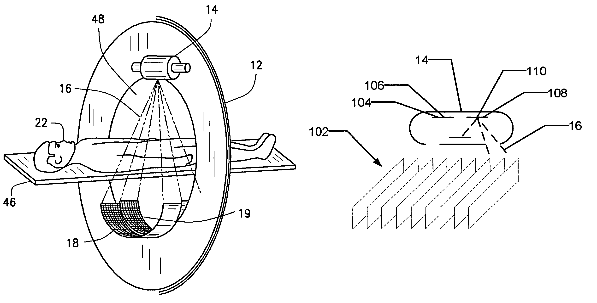
[0012]In some known CT imaging system configurations, an x-ray source projects a fan-shaped beam which is collimated to lie within an X-Y plane of a Cartesian coordinate system and generally referred to as an “imaging plane”. The x-ray beam passes through an object being imaged, such as a patient. The beam, after being attenuated by the object, impinges upon an array of radiation detectors. The intensity of the attenuated radiation beam received at the detector array is dependent upon the attenuation of an x-ray beam by the object. Each detector element of the array produces a separate electrical signal that is a measurement of the beam intensity at the detector location. The intensity measurements from all the detectors are acquired separately to produce a transmission profile.

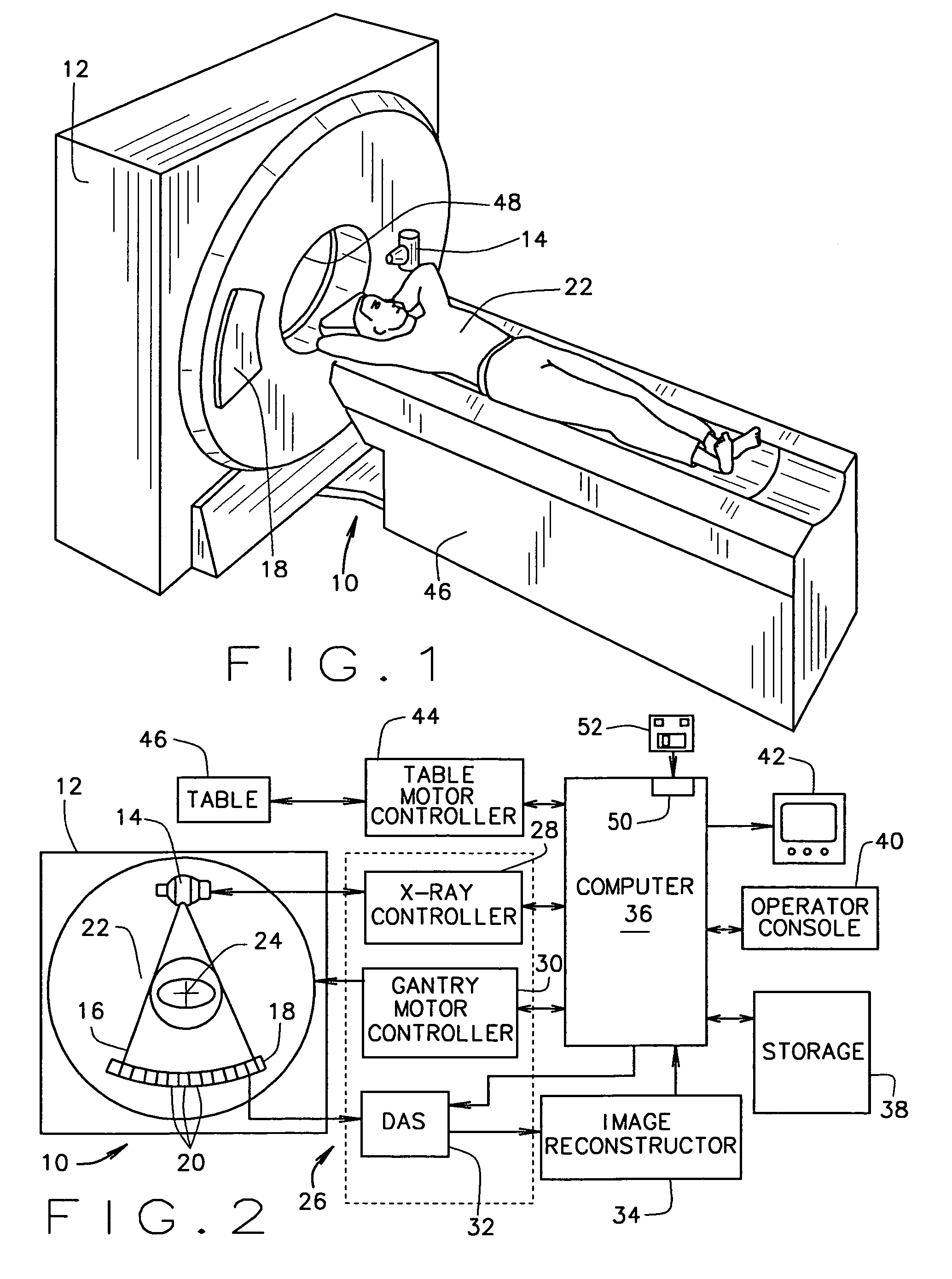
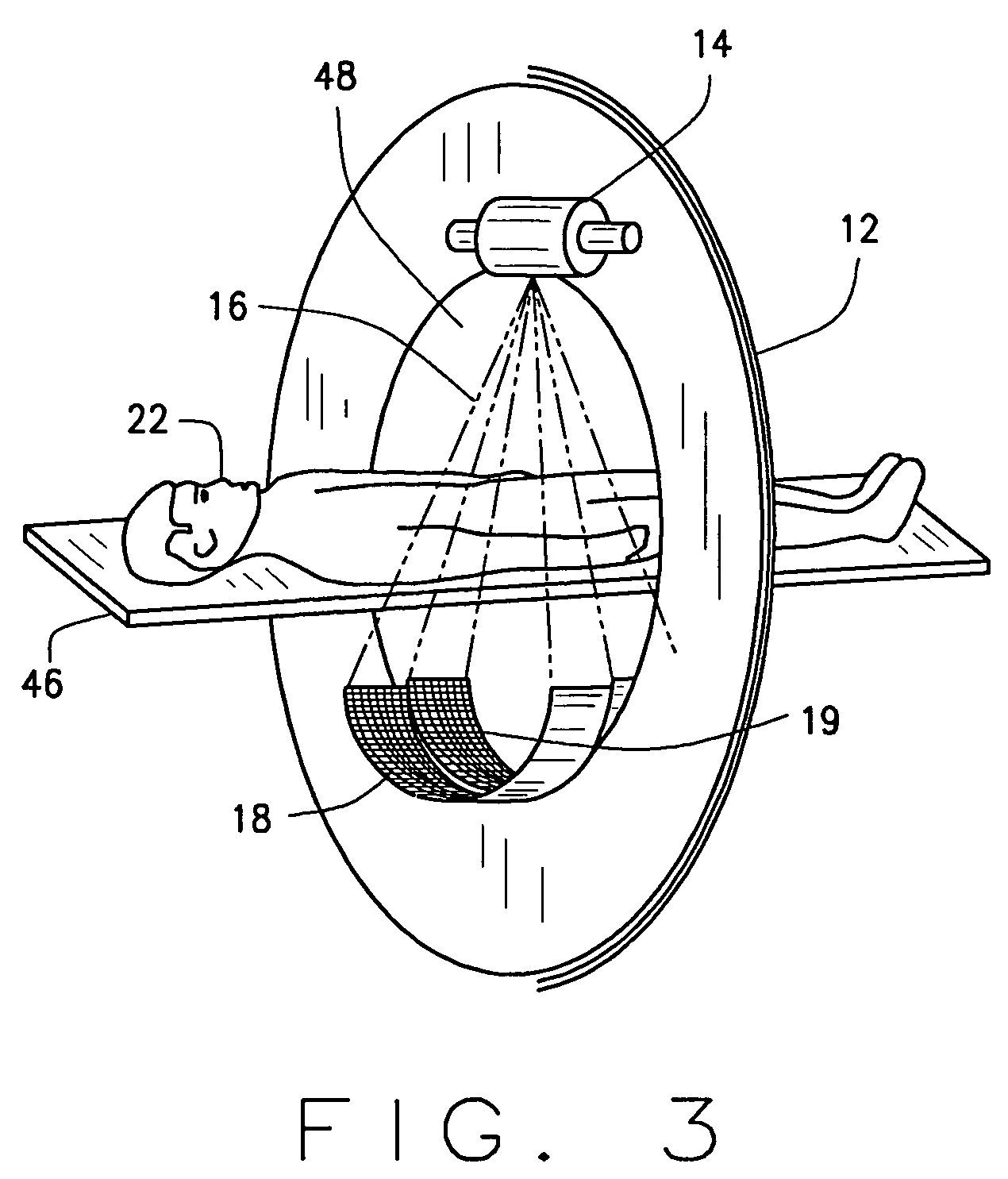
[0013]In third generation CT systems, the x-ray source and the detector array are rotated with a gantry within the imaging plane and around the object to be imaged such that the angle at which the x-ray beam ...


PUM


Abstract

A method for scanning an object to reduce image degradation includes scanning the object in a helical mode using a multi-slice CT imaging system having a plurality of detector arrays arranged along a z-axis direction and a radiation source having a beam focal spot. The method further includes wobbling the focal spot of the radiation source in the z-axis direction during the scanning to selectively preferentially illuminate individual detector arrays through the scanned object for each view. Data is collected from each detector array for each view only when the detector array from which data is being collected is selectively illuminated.

Description

BACKGROUND OF THE INVENTION[0001]This invention relates generally to computed tomographic (CT) imaging methods and apparatus and more particularly to CT methods and apparatus having a plurality of detector arrays.[0002]At least one known CT imaging system utilizes a multi-slice detector array comprising a scintillator and a photodiode arrays. Each detector array contains a plurality of detector cells that are used to measure attenuation information of an object for image back projection for a single or multiple slice planes through the patient. As used herein, a “detector cell” is the smallest portion of a detector array from which attenuation data can be obtained.[0003]At least one known CT imaging system utilizes multi-energy scanning to differentiate tissues or materials having different densities. For example, CT imaging systems have been used to distinguish calcium and iodine in medical applications. One known method uses a single slice image obtained from a CT imaging system h...

Claims


Application Information

Patent Timeline
Patent Type & Authority Patents(United States)
IPC IPC(8): H01J35/24A61B6/03
CPCA61B6/032A61B6/4028A61B6/482A61B6/4085A61B6/4035A61B6/027A61B6/4241
Inventor HOFFMAN, DAVID MICHAEL
Owner GE MEDICAL SYST GLOBAL TECH CO LLC
Why Eureka
Try Eureka