Vehicle interior light source unit

a technology for interior light sources and vehicles, applied in landing aids, lighting and heating apparatus, lighting support devices, etc., can solve the problems of increased size of light source units and inability to install for the interior of vehicles

Active Publication Date: 2010-04-01
TOYODA GOSEI CO LTD
View PDF13 Cites 36 Cited by
  • Summary
  • Abstract
  • Description
  • Claims
  • Application Information

AI Technical Summary

Benefits of technology

[0020]According to one embodiment of the invention, a vehicle interior light source unit is constructed such that a substrate with an LED element mounted thereon is mounted on the main body of a connector portion, and a case is engaged with the sidewall of the main body of the connector portion. Thus, the light source unit can be downsized. Specifically, the connector portion is encompassed inside the case (in top view) such that the entire lig...

Problems solved by technology

However, the light source unit of JP-A-2003-258314 has the problem that the size thereof increases since the connector portion and the case enclosing the LED are arranged in the lateral direct...

Method used


Image

  • Vehicle interior light source unit
  • Vehicle interior light source unit
  • Vehicle interior light source unit

Examples


first embodiment

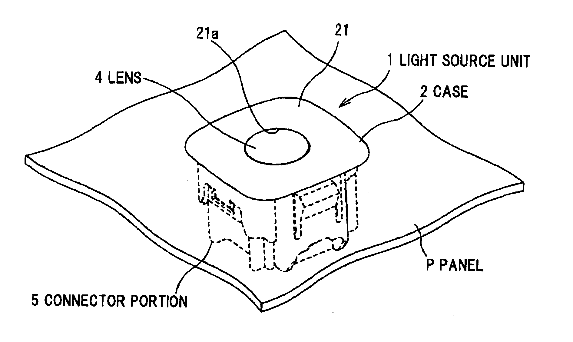
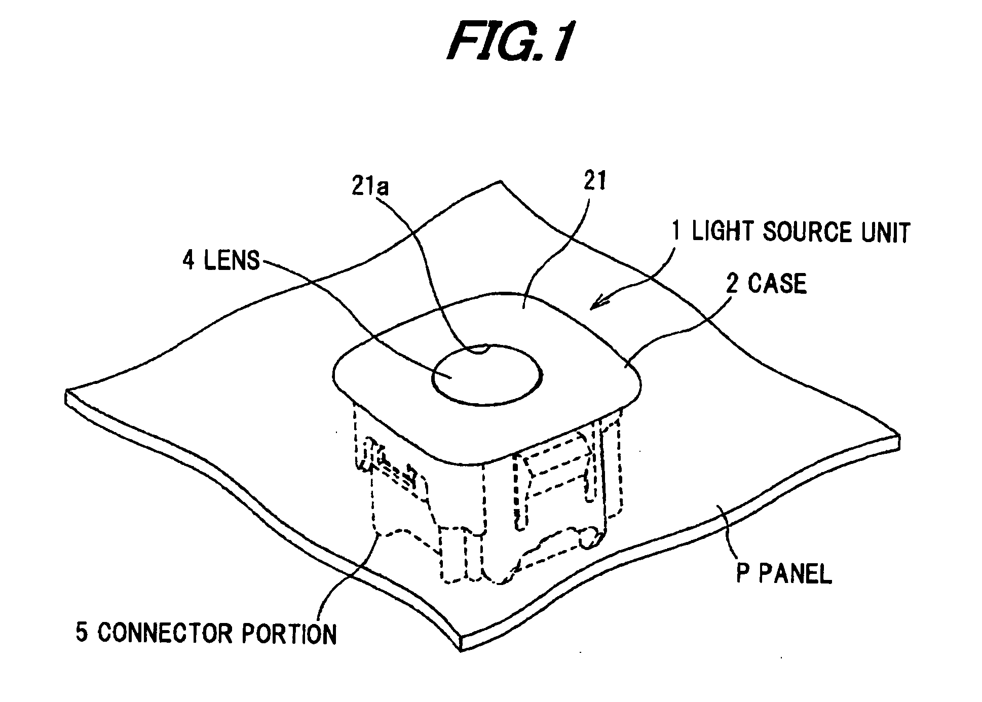
[0033]FIGS. 1 to 6 show the first embodiment of the invention, and FIG. 1 is a perspective view showing a light source unit in the first embodiment, the light source unit being installed in a panel of a vehicle interior.

[0034]As shown in FIG. 1, the light source unit 1 is disposed in an installation hole H (See FIG. 6) formed in a panel P of a vehicle interior such that light from an LED element 3 (not shown in FIG. 1) located inside a case 2 is radiated through a lens 4 to a predetermined area. The light source unit 1 is provided with a connector portion 5 that has a main body 51 (not shown in FIG. 1) disposed on the back side of the panel P and extending parallel to the panel P, and is electrically connected to a harness connector (not shown) to feed current the LED element 3.

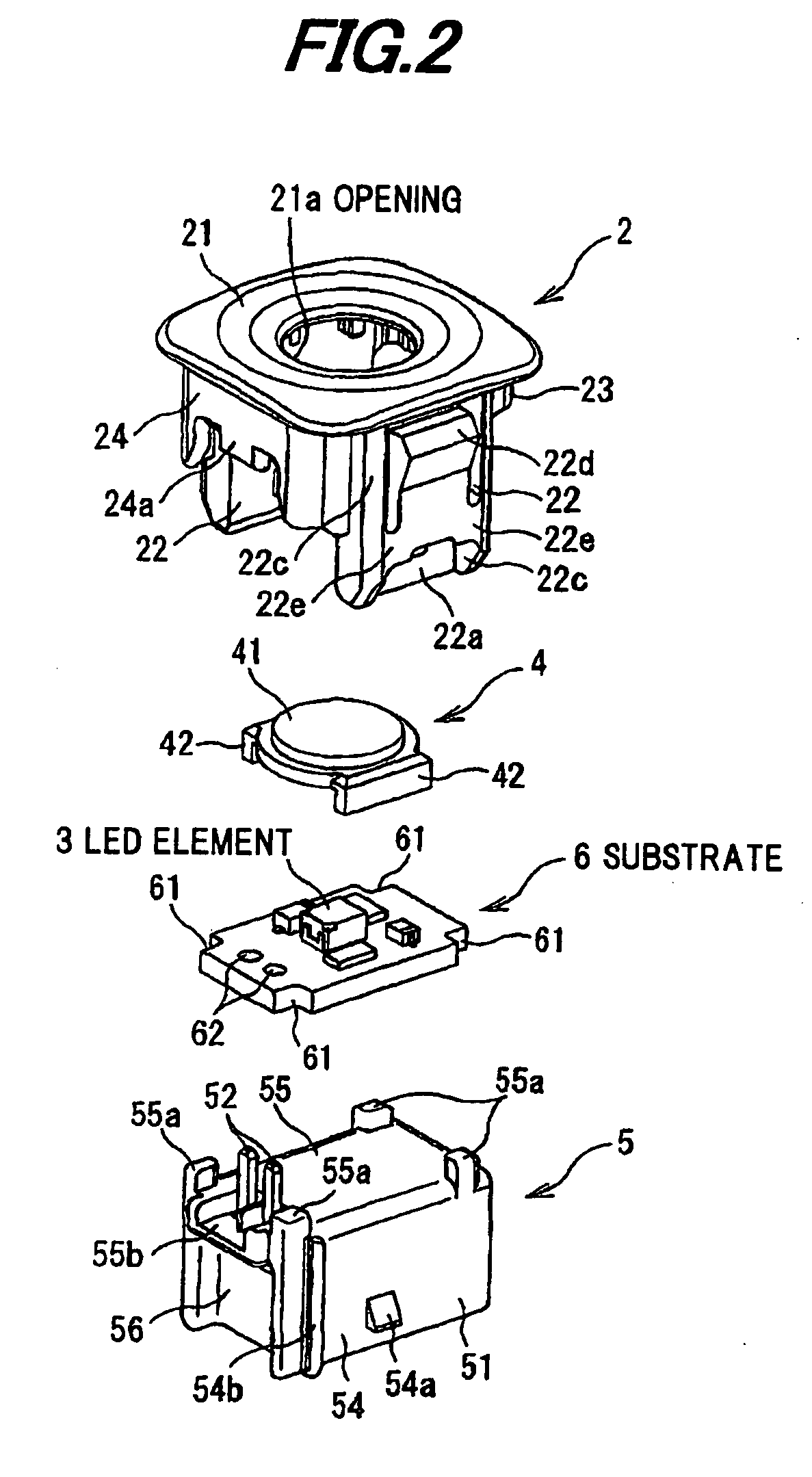
[0035]FIG. 2 is a perspective broken view showing the light source unit.

[0036]As shown in FIG. 2, the light source unit 1 comprises the case 2 to be inserted through the installation hole H formed in the pane...

second embodiment

[0062]FIGS. 8 to 11 show the second embodiment of the invention, and FIG. 8 is a perspective view showing a light source unit in the second embodiment.

[0063]As shown in FIG. 8, the light source unit 101 comprises a case 102 to be inserted through the installation hole H formed in the panel P, a connector portion 105 engaged, with the case 102, a substrate 106 mounted on the connector portion 105, an LED element 103 mounted on the substrate 106, and a lens 104 covering the LED element 103 and disposed over the substrate 106.

[0064]FIG. 9 is a perspective broken view showing the light source unit 101. The case 102 is formed of, e.g., a resin such as PBT, PP, ABS, PA etc. and comprises a upper wall 121 exposed to the vehicle interior from the panel P, a pair of sidewalls 122 disposed laterally and extending downward from the bottom face of the upper wall 121, and a front wall 123 and a back wall 124 extending downward from the outer edge of the upper wall 121. The upper wall 121 has a c...


PUM


Abstract

A vehicle interior light source unit for being disposed at an installation hole formed in a panel of a vehicle interior. The light source unit includes a connector portion that is disposed on a back side of the panel and includes a tubular main body extending parallel to the panel, a substrate that is mounted on the connector portion and mounts a light emitting element thereon, and a case to be inserted into the installation hole. The case includes an upper wall including an opening for radiating light emitted from the light emitting element to the vehicle interior, a pair of sidewalls including a connector engagement portion to be engaged with a side portion of the main boy of the connector portion.

Description

[0001]The present application is based on Japanese patent application No. 2008-251889 filed on Sep. 29, 2008, the entire contents of which are incorporated herein by reference.BACKGROUND OF THE INVENTION[0002]1. Field of the Invention[0003]This invention relates to a light source unit disposed in a panel of a vehicle interior and enabled to connect to a harness connector.[0004]2. Description of the Related Art[0005]A light source unit is known which comprises a connector portion extending laterally, a case disposed laterally adjacent to the connector portion, and an LED (light emitting diode) disposed in the case (JP-A-2003-258314). A circuit part electrically connected to the LED is disposed in the case and the connector portion is attached outside the case.[0006]However, the light source unit of JP-A-2003-258314 has the problem that the size thereof increases since the connector portion and the case enclosing the LED are arranged in the lateral direction. Therefore, it requires a ...

Claims


Application Information

Patent Timeline
IPC IPC(8): B60Q3/00
CPCB60Q3/044B60Q3/0203B60Q3/14B60Q3/51
Inventor ICHIKAWA, TADAOKI
Owner TOYODA GOSEI CO LTD
Why Eureka
Try Eureka