Modular antenna assembly for automotive vehicles

a module antenna and automotive technology, applied in the field of antennas, can solve the problems of increasing design complexity, manufacturing complexity, and inventory complexity, and limiting the application of antennas in the field of automotive vehicles

Active Publication Date: 2008-02-19
RECEPTEC HLDG +1
View PDF8 Cites 33 Cited by
  • Summary
  • Abstract
  • Description
  • Claims
  • Application Information

AI Technical Summary

Benefits of technology

[0004]The aforementioned problems are overcome in the present invention comprising a modular antenna assembly for automotive vehicles. The antenna assembly includes a base assembly that is suitable for installation on a wide variety of vehicle platforms and a radome assembly unique to a particular vehicle platform. The radome assembly can be easily yet securely attached to the base assembly during or subsequent to installation of the base assembly on the vehicle.

Problems solved by technology

An antenna designed for one platform typically will not be acceptable for mounting on a different platform having a different shape.
The need to have unique antennas for unique vehicles undesirably increases design complexity, manufacturing complexity, and inventory complexity.

Method used


Image

  • Modular antenna assembly for automotive vehicles
  • Modular antenna assembly for automotive vehicles
  • Modular antenna assembly for automotive vehicles

Examples


Embodiment Construction

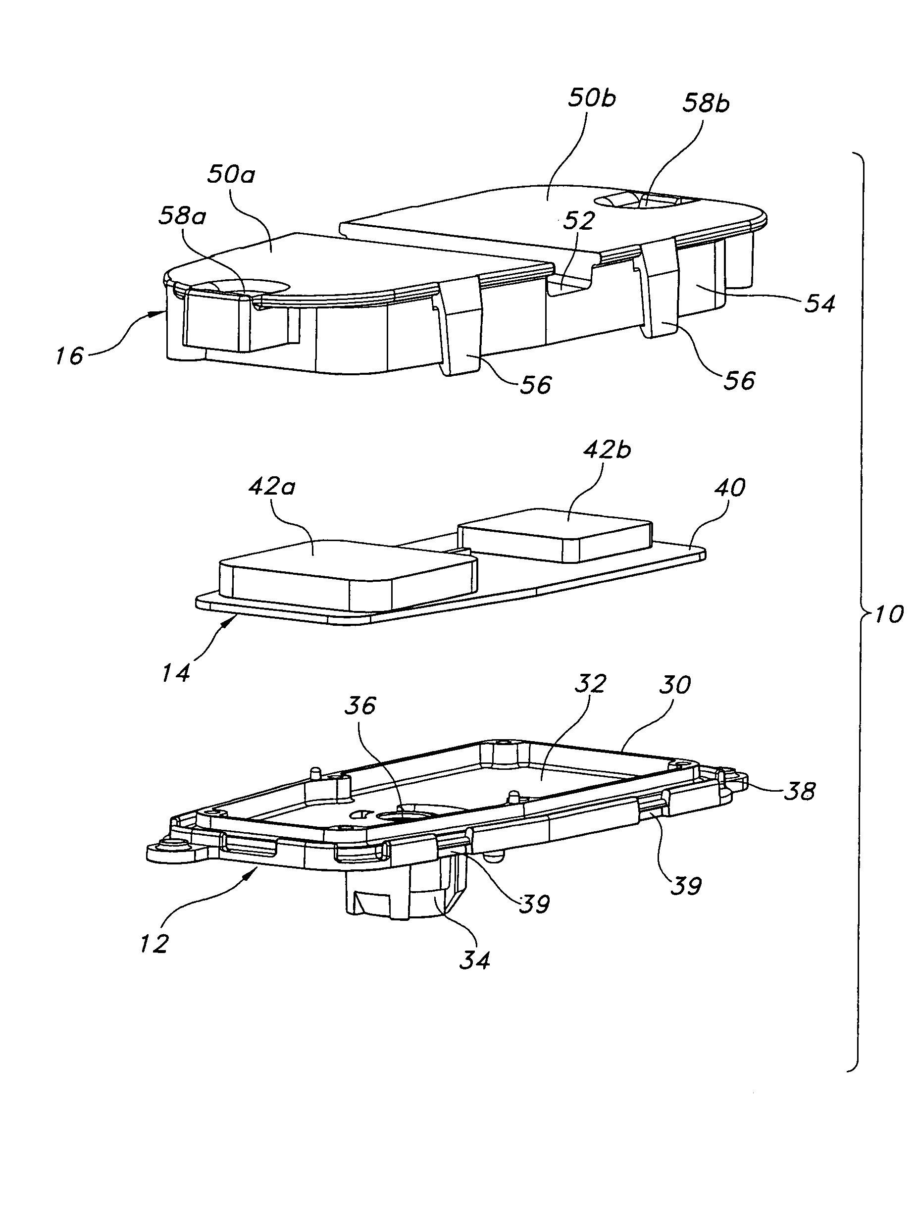
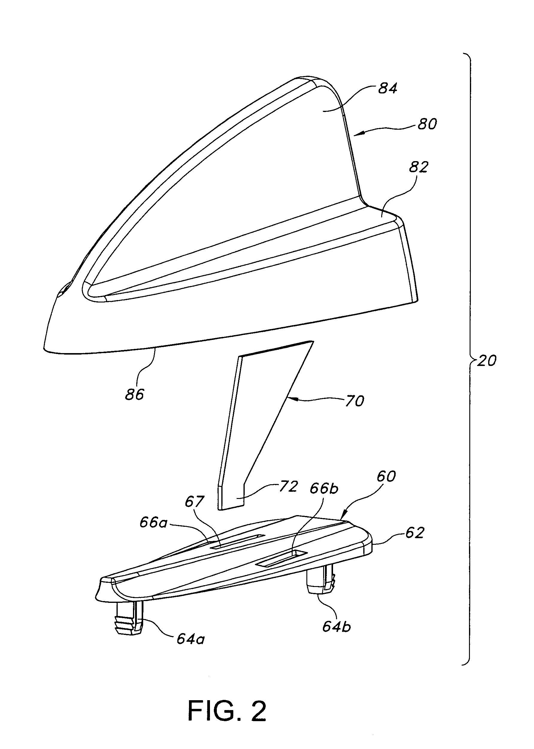
[0019]An antenna assembly constructed in accordance with a preferred embodiment of the invention is illustrated in the drawings. The antenna assembly includes a base assembly 10 (FIGS. 1 and 3) an a radome assembly 20 (FIGS. 2 and 4). When installed on a vehicle, the base assembly 10 is secured directed to the vehicle body panel, and the radome assembly 20 is snap-fitted onto the base assembly.

I. Base Assembly

[0020]The base assembly 10 is illustrated in FIG. 1 (exploded) and FIG. 3 (assembled). The base assembly includes a chassis 12, a printed circuit (PC) board assembly 14, and a base cover 16.

[0021]The chassis 12 is die cast of zinc, although other manufacturing processes and materials may be used. The chassis includes a generally planar body 30 defining a pocket 32 in its upper surface. An attachment stud or lug 34 extends from the underside of the body 30 for attachment to a vehicle body panel in conventional fashion. The lug 34 defines a central aperture 36 extending through t...


PUM


Abstract

The specification discloses a modular antenna for automotive vehicles. The antenna includes a base assembly that can be used on a variety of vehicle platforms and a radome assembly that is specific to a particular vehicle platform. The radome assembly snap-fits onto the base assembly, and can be installed during or after vehicle assembly. A wide variety of radome assemblies of different shapes, styles, and colors can be used in conjunction with a single base assembly.

Description

BACKGROUND OF THE INVENTION[0001]The present invention relates to antennas, and more specifically to antennas for automotive vehicles.[0002]A wide variety of antennas have been developed for automotive vehicles. The antennas are adapted to receive signals in a variety of formats, including but not limited to AM radio, FM radio, satellite radio, global positioning system (GPS), cell phones, and citizens band (CB). Often the antennas are designed for a specific location on the vehicle. For example, antennas for receiving circularly polarized signals, such as those associated with satellite radio and GPS, are typically mounted on the vehicle roof.[0003]An antenna designed for installation on a vehicle body panel, such as the vehicle roof, must address a variety of issues in addition to receiving signals. First, the antenna should be aesthetically pleasing—at least to the extent possible in view of its functionality. Second, the antenna should conform closely to the body panel on which ...

Claims


Application Information

Patent Timeline
Patent Type & Authority Patents(United States)
IPC IPC(8): H01Q1/32
CPCH01Q1/3275
Inventor LINDACKERS, RALFYASIN, HASANFUCHS, ANDREAS D.DUZDAR, AYMAN
Owner RECEPTEC HLDG
Why Eureka
Try Eureka