Electric vehicle and on-board battery charging apparatus therefor

a charging apparatus and electric vehicle technology, applied in the direction of batteries/cells, couplings, machines/engines, etc., can solve the problems of axial tolerance problems, inability to absorb the required increasing dynamic torque, and substantial rotary imbalances and deformation, so as to achieve efficient length adjustment

Active Publication Date: 2011-06-30
SWISSAUTO POWERSPORT
View PDF48 Cites 30 Cited by
  • Summary
  • Abstract
  • Description
  • Claims
  • Application Information

AI Technical Summary

Benefits of technology

[0012]Another object is to enable the generator to serve as the flywheel mass of the engine, reducing both the cost and the weight.
[0013]Another object is to provide minimum weight to the engine by eliminating such peripheral components as a tradition oil pump. Rather, a method of providing a “pump” from suction created during the compression stroke is shown herein.
[0017]With the present design in accordance with the drawings, the generator is suitable for the mounting to different engines, whereby the coupling can in principle be made by any chosen connection of the shafts and the housing. Engine and generator are independent and are connected by a connecting member. For a single-cylinder engine with a very short crank shaft, this design is the most sensible solution because of the separate bearing of the generator rotor allows the air gap in the generator to be kept small in order to achieve a high efficiency. The bending moment in the crank shaft during combustion, as well as the bearing clearances on the short distance between the bearings can in an appropriate arrangement be carried by the generator bearing, thus preventing contact of the rotor and the housing.
[0020]In one embodiment, a serial hybrid electric vehicle is coupled with a combustion engine which serves to extend the operating range. The combustion engine is coupled to the generator of the range extender by a self-centering spur gearing.
[0021]In another embodiment of the invention, a serial hybrid electric vehicle is coupled with combustion engine which serves to extend the operating range. A crankshaft of the engine is fixedly connected to a shaft of the generator. A fixed bearing and a first floating bearing are located on the side of the generator and the bearings on the side of the engine are configured as floating bearings in order to absorb the length extensions of the shafts caused by temperature influence.
[0032]In another embodiment, an electric vehicle, comprises a chassis; a drive axle coupled to the chassis; an electric motor configured to drive the drive axle; a battery configured to drive the electric motor; an engine generator configured to generate electrical power and to provide electrical power generated to the battery; and a mass supported by the engine to dampen vibrations of the engine.

Problems solved by technology

A first factor of such aggregates is the coupling of the combustion engine to the generator, because the high combustion power of the engine causes substantial rotary imbalances and deformation on the crank shaft.
These couplings also cannot absorb the required increasing dynamic torque.
Furthermore, axial tolerances are problematic because during the assembly, the mounting position dependent on the tightening torque cannot be exactly determined.
Assembly and removal are also made more difficult.
These connections however are complex to manufacture; the generated momentum provoke a mechanical play and running noise if a thrust tolerance is used; assembly and removal are problematic with crimp connections; and assembly length / space requirements are relatively high.

Method used


Image

  • Electric vehicle and on-board battery charging apparatus therefor
  • Electric vehicle and on-board battery charging apparatus therefor
  • Electric vehicle and on-board battery charging apparatus therefor

Examples


Embodiment Construction

[0073]The embodiments disclosed herein are not intended to be exhaustive or limit the disclosure to the precise forms disclosed in the following detailed description. Rather, the embodiments are chosen and described so that others skilled in the art may utilize their teachings.

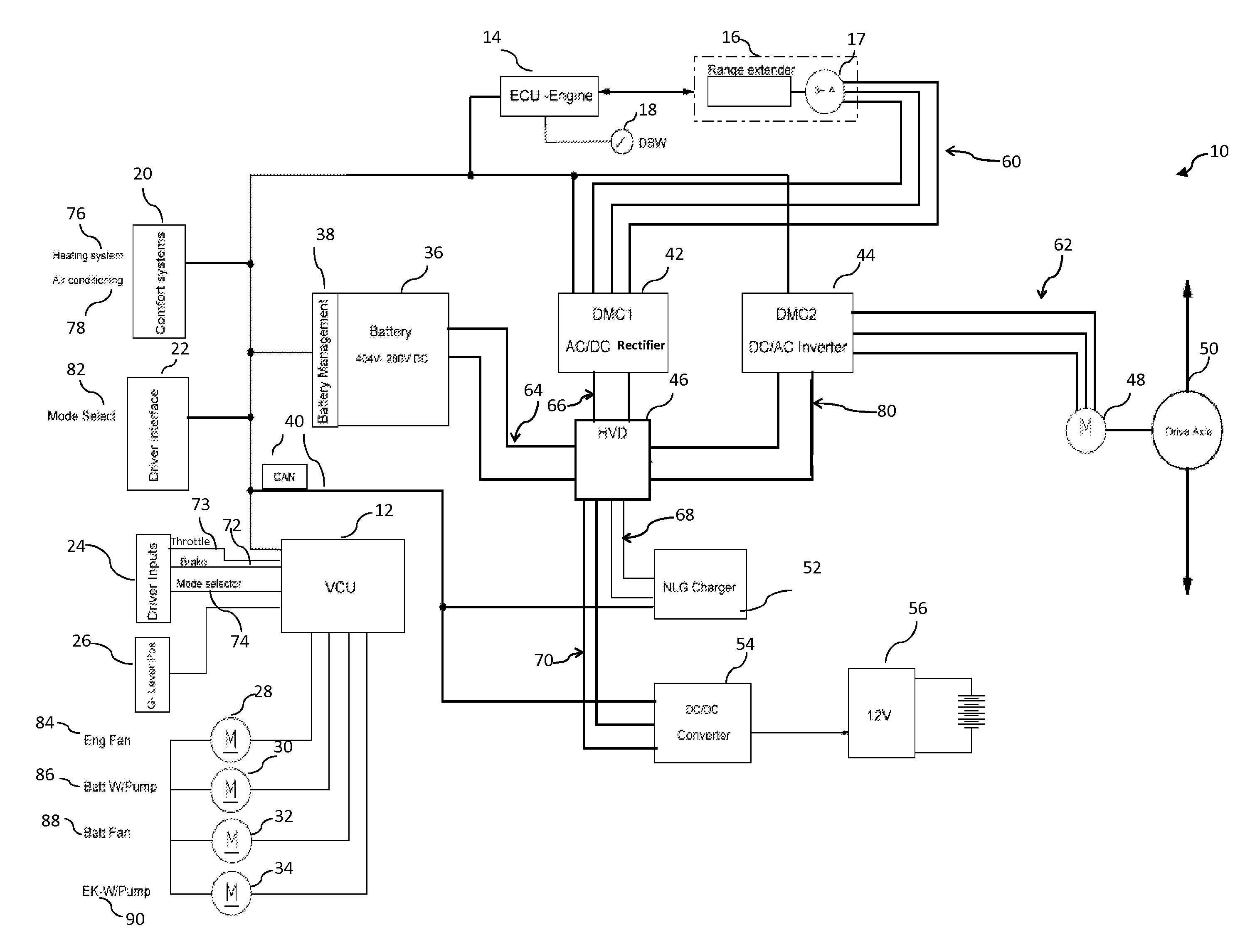
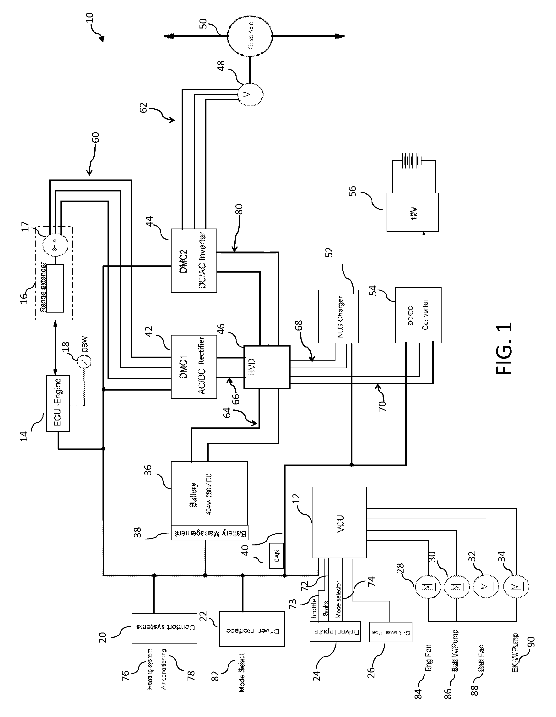
[0074]Referring initially to FIG. 1, an electrical system 10 is shown for controlling the operation of an electric vehicle. The electric vehicle may be a car, an all-terrain vehicle, a sport utility vehicle, a watercraft, or any other suitable vehicle. In the illustrated embodiment, electrical system 10 is configured for use with a car. Electrical system 10 includes a vehicle battery 36 that provides electrical power to a vehicle motor 48 for driving a drive axle 50 of the electric vehicle. A range extender 16 serves to generate electrical power for utilization in electrical system 10, such as for charging vehicle battery 36 or for powering vehicle motor 48 of the electric vehicle. Electrical system 10 include...


PUM


Abstract

An electric vehicle and a range extender engine are shown including the controls to operate the same.

Description

[0001]This application is a continuation of PCT Application Serial No. PCT / US2010 / 049167.FIELD OF THE INVENTION[0002]The subject disclosure relates to electric vehicles and a charging system therefore, and in particular, an onboard engine generator for charging the battery packs. The vehicle has extended operating range with coupled combustion engine, whereby it concerns a serial hybrid electric vehicle according to the EC-Directives.BACKGROUND OF THE INVENTION[0003]Electric vehicles are known having battery packs which drive an electric motor which in turn drives the vehicle wheels. Two types of vehicles are known using electric motors, the first is a hybrid electric vehicle where the vehicle includes an electric motor and an onboard fuel driven engine, where the engine is used to drive the wheels under certain vehicle circumstances.[0004]Another type of electric vehicle also has an onboard fuel driven engine, but the engine is only used to drive a generator, which in turn charges ...

Claims


Application Information

Patent Timeline
Patent Type & Authority Applications(United States)
IPC IPC(8): F01L3/00F02F7/00B60L50/15
CPCY02T10/6217Y02T10/6286Y02T10/7005B60W2510/246B60W10/08B62M3/003F16D3/18B60L11/126B60K6/36B60W2520/10B60W2540/10B60K6/405F16D1/076B60K6/40B60W2540/12Y02T10/7077B60K6/24B60W20/00Y10T477/30Y02T10/6295F16F1/376B60W10/06B60W10/26B60K6/38B60K6/46F16D1/10Y10T477/23B60W2510/244B60L50/62Y02T10/40Y02T10/62Y02T10/70B60W20/13Y02T10/7072
Inventor WENGER, URSKOHLER, BEAT RENEJENNI, HANS-RUDOLPH
Owner SWISSAUTO POWERSPORT
Why Eureka
Try Eureka