Pneumatic Tire

a pneumatic tire and tire body technology, applied in the field of pneumatic tires, can solve the problems affecting the stability the pneumatic tire has no inclined plane, so as to increase the ice braking performance of the pneumatic tire, increase the dry steering stability performance, and prevent the effect of reducing the rigidity of the land portion forming the sip

Inactive Publication Date: 2010-04-08
TOYO TIRE & RUBBER CO LTD
View PDF3 Cites 49 Cited by
  • Summary
  • Abstract
  • Description
  • Claims
  • Application Information

AI Technical Summary

Benefits of technology

[0010]According to the above-described pneumatic tire, each of the pluralities of sipes extending in the width direction of the tire include a wide portion having an inclined plane that begins from the tread surface of the road surface, and terminates in the half way of the sipe wall while inclining so that a sipe width decreases toward the groove bottom of the sipe. Therefore, the edge portion of the inclined plane generates a large ground pressure, and thereby the edge effect acting in the circumferential direction of the tire accordingly increases. Further, the sipe includes the pluralities of wide portions that are located alternately on the both sipe walls along the longitudinal direction of the sipe. Therefore, at braking and accelerating on an icy road surface, the edge effect acting due to the edge portion of the inclined plane increases. Furthermore, when the sipe includes the pluralities of wide portions located alternately on the both sipe walls along the longitudinal direction of the sipe, the inclined plane can be arranged to have a large inclination angle with respect to the sipe walls while preventing the rigidity of the land portion forming the sipe from being reduced. As a result, particularly, the ice braking performance of the pneumatic tire is increased while increasing the dry steering stability performance.
[0011]Also, in the above-described pneumatic tire, the sipe includes the pluralities of wide portions having the pair of side faces connecting the inclined plane and the sipe walls. Therefore, the edge portion of the side faces generates a large ground pressure as well as the edge effect acts in the width direction of the tire (turning directions). As a result, the ice turning performance of the pneumatic tire is increased.
[0012]In the above-described pneumatic tire, it is preferred that the pair of side faces of the wide portion incline toward the groove bottom of the sipe so that the length of the inclined plane deceases. In the pneumatic tire as described above, the sipe includes the pluralities of wide portions in which the pair of side faces inclining toward the groove bottom of the sipe so that the length of the inclined plane decreases. Therefore, particularly, the edge portions of the side faces generate a large ground pressure, and the edge effect acting in the turning directions is further increased. As a result, the ice turning performance of the pneumatic tire is particularly increased.

Problems solved by technology

As a result, the steering stability on dry surface (hereinafter, referred to as “dry steering stability performance”) decreases, or the blocks tend to wear unevenly in the front and rear portions thereof.
However, the pneumatic tire has no inclined plane at the opening side of the sipe.
Therefore, the edge effect of the sipe is insufficient and the tire has a point to be further improved in both of ice braking performance and ice turning performance.
Therefore, the block formed with the sipe tends to lose the rigidity and dry steering stability performance is easily reduced; or the blocks tend to be worn unevenly in the front and rear portions thereof.
However, these pneumatic tires fail in obtaining sufficient edge effect by the sipes.

Method used


Image

  • Pneumatic Tire
  • Pneumatic Tire
  • Pneumatic Tire

Examples


examples 1 to 6

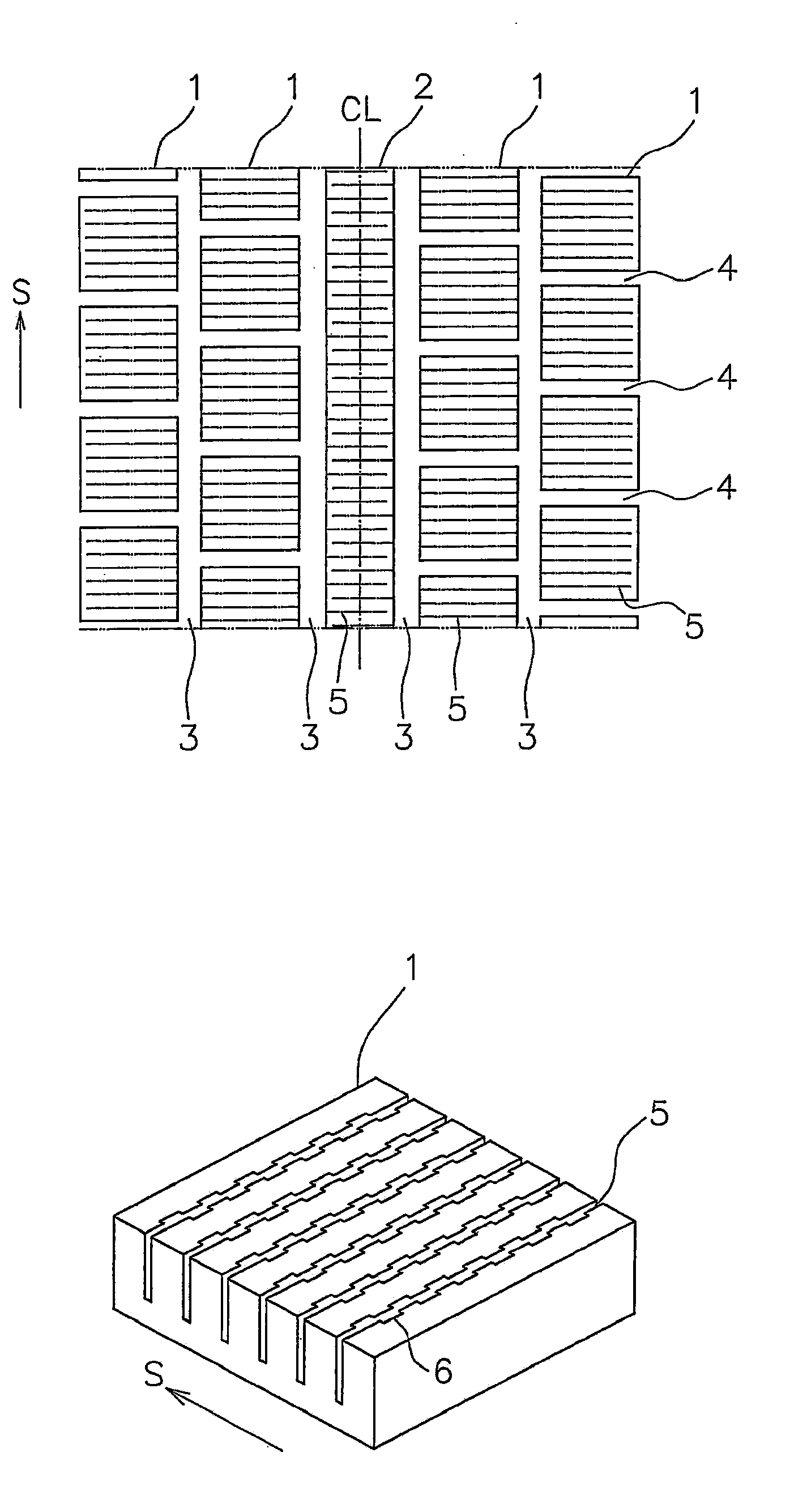
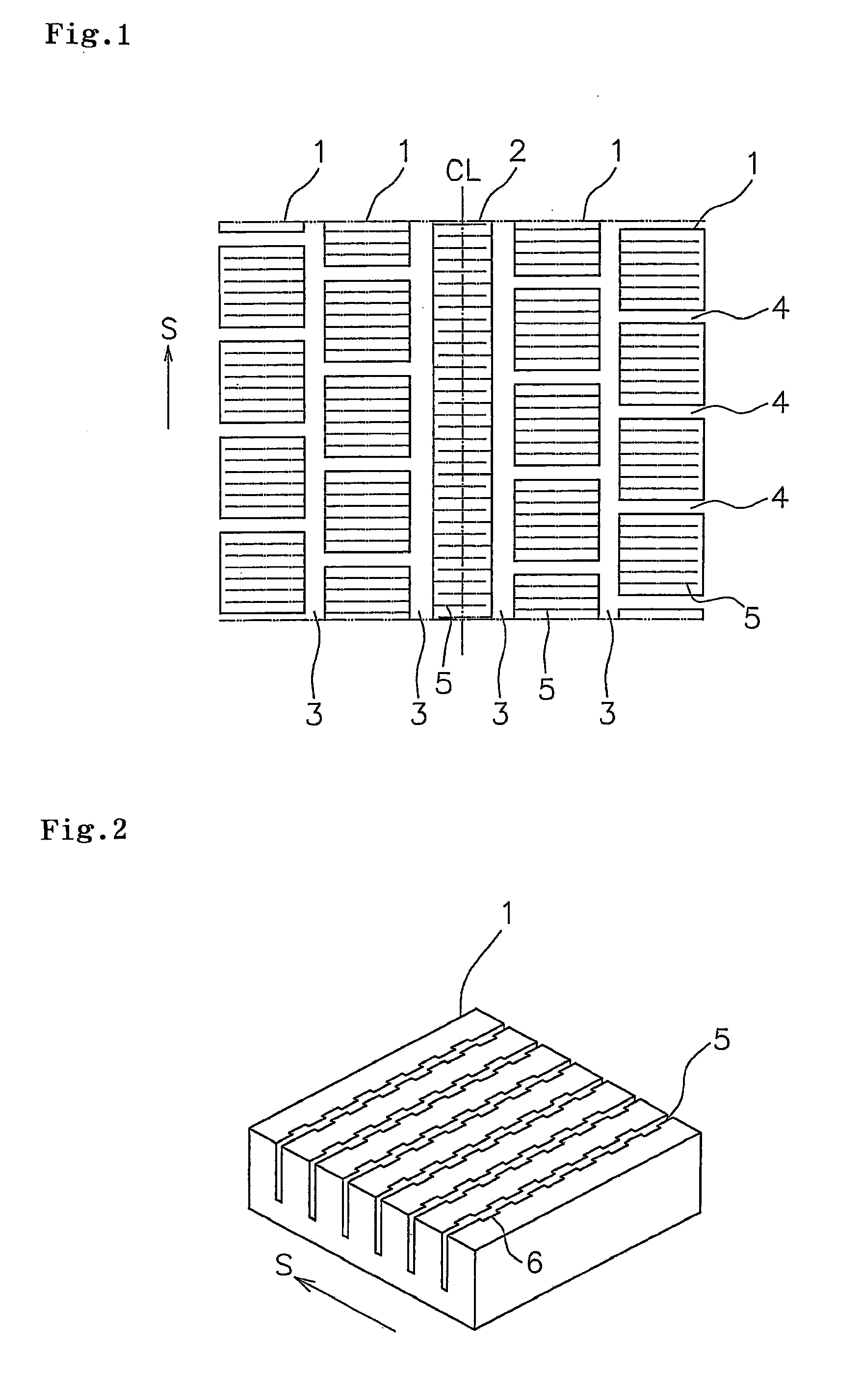
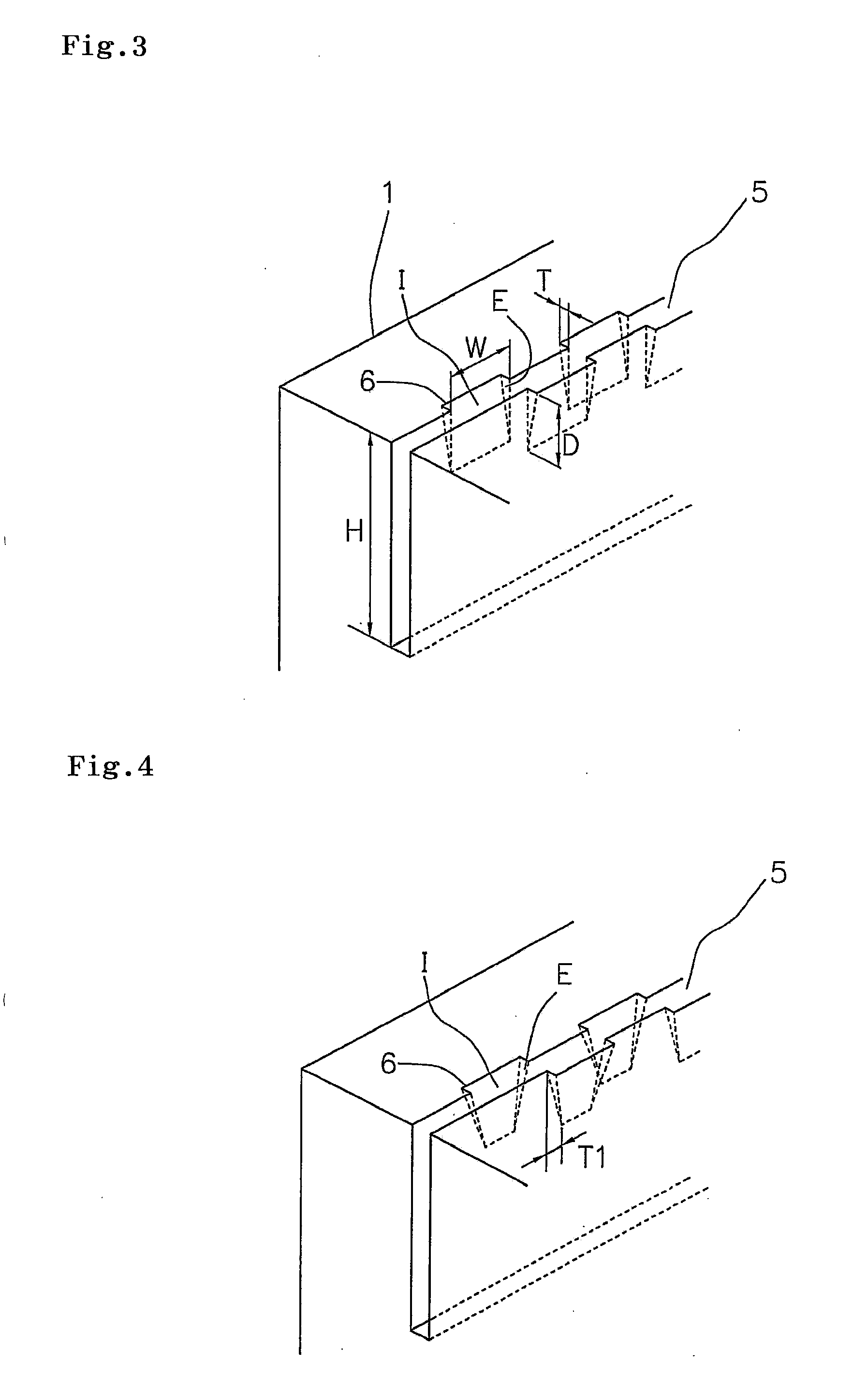
[0040]In pneumatic tires shown in FIGS. 1 to 3, each of the pneumatic tires with the same structure as that of the Comparative Example 1 was manufactured except a point that each of the sipe 5 include the wide portion 6 in which the length W of each of the inclined planes I on the tread surface of the road surface extending in the longitudinal direction of the sipe, a length T of each of the side faces E on the tread surface of the road surface, and a depth D of each of the inclined planes I on the tread surface of the road surface, were set to the dimensions as listed in Table 1. Using the above tires, the evaluation was made on the respective performances. The results are shown in Table 1.

example 7 to 8

[0041]Each of pneumatic tires with the same structure as that of the Examples 1 to 6 was made except a point that a length T1 of the respective side faces E in the longitudinal direction was set to the dimensions listed in Table 1, each of the sipes 5 has pluralities of wide portions 6 shown in FIG. 4. Using the above tires, the evaluation was made about the respective performances. The results are shown in Table 1.


PUM


Abstract

An object of the present invention is to provide a pneumatic tire capable of ensuring both of the ice braking performance and the ice turning performance while increasing the dry steering stability performance. To achieve the above object, a sipe extending in a width direction of the tire is formed a land portion, the sipe having: pluralities of wide portions each having an inclined plane that begins from the tread surface of a road surface, and terminates in the half way of a sipe wall while inclining so that a sipe width decreases toward the groove bottom of the sipe, and a pair of side faces connecting the inclined plane and the sipe wall therebetween, wherein the pluralities of wide portions are located alternately on both sipe walls along a longitudinal direction of the sipe.

Description

BACKGROUND OF THE INVENTION[0001]1. Field of the Invention[0002]The present invention relates to a pneumatic tire comprising a tread surface including a land portion in which a sipe extending in a width direction of the tire is formed, more particularly to a pneumatic tire useful as a winter tire.[0003]2. Description of the Related Art[0004]Conventionally, winter tires have a land portion such as a block and a rib formed with pluralities of cuts called as sipes therein. These sipes generate edge effect and water removal effect and increase running performance of a tire on an icy road surface, which has a small friction coefficient (hereinafter, referred to as “ice performance”). As such sipes, straight sipes extending straight along a longitudinal direction thereof, wave-like sipes extending in a wave-like shape, or the like are practically used.[0005]For example, Japanese Patent Application Laid-Open Publication No. 2007-223493 described below discloses a pneumatic tire as describe...

Claims


Application Information

Patent Timeline
Patent Type & Authority Applications(United States)
IPC IPC(8): B60C11/13
CPCB60C11/1281B60C11/12
Inventor MIYAZAKI, TETSUJIASAYAMA, YOSHINORI
Owner TOYO TIRE & RUBBER CO LTD
Why Eureka
Try Eureka