Method for the multipath passive radar processing of an FM opportunity signal

a technology of opportunity signal and passive radar, applied in direction finders using radio waves, instruments, reradiation, etc., can solve the problems of complex and expensive deployment of such a set of autonomous radar systems, complex implementation of transmitter and means of synchronization between transmitter and receiver, and complexity of the signal received

Active Publication Date: 2010-04-08
THALES SA
View PDF1 Cites 18 Cited by
  • Summary
  • Abstract
  • Description
  • Claims
  • Application Information

AI Technical Summary

Problems solved by technology

Furthermore the deployment of such a structure even over a vast zone generally poses problems of closeness between systems covering neighboring zones within one and the same global geographical zone.
Nevertheless, the deployment of such a set of autonomous radar systems is both complex and expensive.
Nevertheless such a structure which requires in particular the installation of a transmitter and means of synchronization between the transmitter and the various receivers remains complex to implement especially in the case of a mobile structure.
On the other hand the practical implementation of this purely passive solution comes up against a certain number of difficulties which explain why they are still little utilized.
A first difficulty which appears when one wishes to implement such a structure resides in the complexity of the signal received.
The complexity of the signal received is moreover further exacerbated by the reception of spurious signals that may for example originate from other, distant, transmitters transmitting in the same frequency band.
Another difficulty related to the implementation of such a structure resides in the fact that the opportunity transmission corresponds to an unknown signal whose properties are not controlled (bandwidth, level of the distance and Doppler sidelobes, etc.).

Method used


Image

  • Method for the multipath passive radar processing of an FM opportunity signal
  • Method for the multipath passive radar processing of an FM opportunity signal
  • Method for the multipath passive radar processing of an FM opportunity signal

Examples


Embodiment Construction

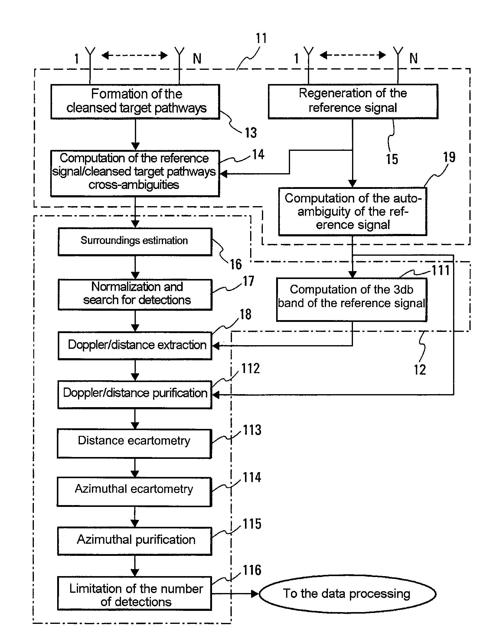
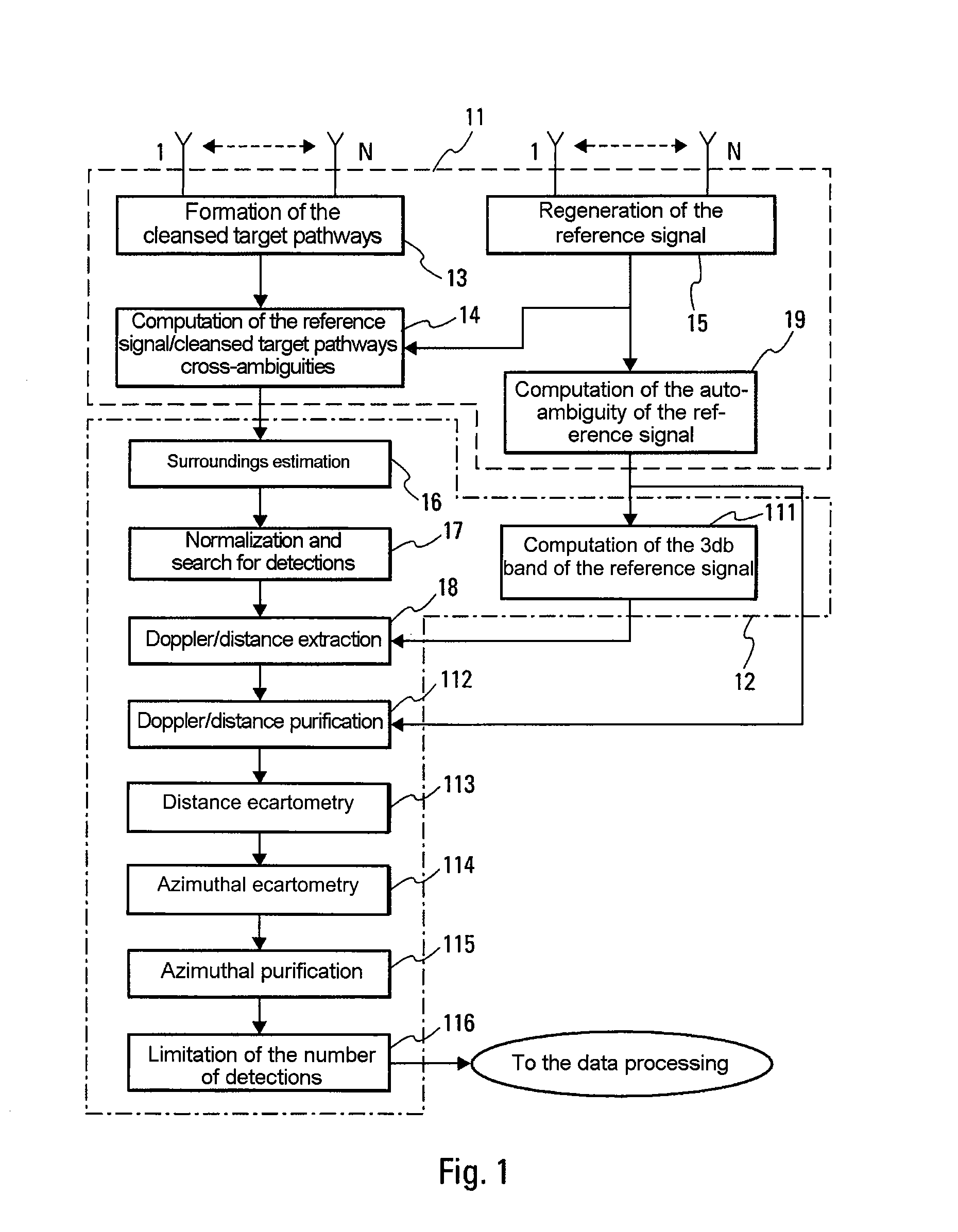
[0030]Attention is first turned to FIG. 1, which presents the typical schematic overview of a signal processing method implementing one or more embodiments of the invention. The method according to one or more embodiments of the invention is here presented in its nonlimiting application to a passive radar including a plurality of independent reception pathways. To facilitate the understanding of the invention, the method is firstly presented in a general manner with all its processing steps. The steps enclosed in bold, specific to the invention, are detailed subsequently in the document. The other steps implementing known methods are simply mentioned so as to facilitate the description of the method which combines all of these steps.

[0031]As illustrated by FIG. 1, the method according to the invention implements two types of processing, a first type of processing 11, dubbed, in a manner known to the person skilled in the art, coherent processing which undertakes a re-conditioning of...


PUM


Abstract

The present invention relates to the field of passive radars, and more particularly the field of the processing of the signals utilized by such radars. The signal processing method received according to one or more embodiments of the invention performs coherent processing, in order to purge spurious signals from the useful signal, including the reference signal and its multiple reflections, to regenerate the transmission signal and to perform a coherent integration of the signal received, by computing the cross-ambiguity between the signal received and the regenerated transmission signal. One or more embodiments of the invention also performs operations of non-coherent processing making it possible in particular to carry out extraction and Doppler distance purification operations making it possible to form blips and to eliminate the spurious blips present among the blips formed. The invention applies to passive radars operating on non-cooperating opportunity transmissions, such as FM transmissions intended for the public.

Description

CROSS-REFERENCE TO PRIOR APPLICATION[0001]This is a U.S. National Phase Application under 35 U.S.C. §371 of International Application no. PCT / EP2007 / 063830, filed Nov. 12, 2007, and claims benefit of French Patent Application No. 06 10811, filed Dec. 12, 2006, both of which are incorporated herein. The International Application was published in French on Jun. 19, 2008 as WO 2008 / 071745 under PCT Article 21 (2).FIELD OF THE INVENTION[0002]The present invention relates to the field of passive radars, and notably the field of passive radars operating on non-cooperating opportunity transmissions, such as FM transmissions intended for the public. It deals more particularly with the processing of the FM signals reflected by objects situated in the zone covered by such transmissions for their use for detection and location purposes.CONTEXT OF THE INVENTIONPrior Art[0003]When one wishes to achieve the radar coverage, temporary or permanent, of a geographical zone, the immediate solution gen...

Claims


Application Information

Patent Timeline
Patent Type & Authority Applications(United States)
IPC IPC(8): G01S13/00
CPCG01S13/003G01S7/356G01S7/352
Inventor DE GRAMONT, EMMANUELDESODT, GUYALLAM, SEBASTIEN
Owner THALES SA
Why Eureka
Try Eureka