Control device for vehicular drive apparatus

a control device and vehicular drive technology, applied in the direction of engine-driven generators, machine/engine control, process and machine control, etc., can solve the problems of increasing the number of components, the large size of the vehicular drive apparatus as a whole, and the likelihood of an increase in gearshift shock, etc., to suppress the shifting shock

Active Publication Date: 2010-04-08
TOYOTA JIDOSHA KK
View PDF7 Cites 25 Cited by
  • Summary
  • Abstract
  • Description
  • Claims
  • Application Information

AI Technical Summary

Benefits of technology

[0019]According to the first aspect of the present invention, during the concurrent shifting when the downshift in one of the first shifting portion and the second shifting portion and the upshift in the other of the first shifting portion and the second shifting portion are executed at the same time, the shifting progress state is controlled by controlling the rotation speed of the rotary element. Consequently, the shift directions can be fixed to be unidirectional during the shifting in the vehicular drive apparatus, which can suppress the shifting shock. During the concurrent shifting, for instance, controlling the rotation speed of the rotary element by the electric motor enables a shifting progress state of the other of the first shifting portion and second shifting portion to be controlled with respect to a shifting progress state of one of the first shifting portion and the second shifting portion. This can execute the shifting of the other of the first shifting portion and second shifting portion conjunction with the shifting in one of the first shifting portion and second shifting portion, thereby suppressing the shifting shock.
[0020]Preferably, in the control device of a vehicular drive apparatus, the shifting progress state of one of the first shifting portion and the second shifting portion with respect to the state of shifting progress of the other of the first shifting portion and the second shifting portion upon the concurrent shifting is controlled by controlling the rotation speed of the electric motor. This can suppress the shifting shock.
[0021]Preferably, in the control device of a vehicular drive apparatus, the electric motor is controlled to commence and complete the shifting in the first shifting portion during an inertia phase of the shifting in the second shifting portion. This can conceal a variation in rotations by the shifting of the first shifting portion in a variation in rotations caused by the shifting of the second shifting portion, for thereby suppressing the shifting shock.
[0022]Preferably, in the control device of a vehicular drive apparatus, the first electric motor is connected to the rotary element of the first shifting portion as the electric motor, and the first electric motor controls the rotation speed of the rotary element in the first shifting portion. With such structure, the shifting progress state can be appropriately controlled for the concurrent shifting.
[0023]Preferably, in the control device of a vehicular drive apparatus, the first electric motor is controlled depending on the variation in numbers of the input rotation of the second shifting portion during the concurrent shifting. This can execute the shifting of the first shifting portion in a mode suited for the shifting progress state in the second shifting portion. That is, as the second shifting portion begins to perform the shifting, the input rotation speed of the second shifting portion begins to vary. Thus, controlling the rotation speed of the rotary element of the first shifting portion by the first electric motor enables the first shifting portion to execute the shifting in conformity to the state of progress of the shifting in the second shifting portion.
[0024]Preferably, in the control device of a vehicular drive apparatus, the first shifting portion and the second shifting portion are disposed in the power transfer path extended between the engine of the vehicle and the drive wheels, and the electric motor is controlled to allow rotation speeds of the engine to vary in the same direction during the concurrent shifting. Thus, no fluctuation occurs in the engine rotation speed during the concurrent shifting, and the single shifting is recognized for the vehicular drive apparatus as a whole, thereby precluding a driver from having an uncomfortable feeling.

Problems solved by technology

This increases the number of component parts with a likelihood of causing the vehicular drive apparatus to be large-sized as a whole.
Unless such a shift control is properly performed, there is a likelihood of an increase in gearshift shock.
Thus, unless a need arises to properly perform the shift control, it is likely that gearshift shock will increase.

Method used


Image

  • Control device for vehicular drive apparatus
  • Control device for vehicular drive apparatus
  • Control device for vehicular drive apparatus

Examples


embodiment 1

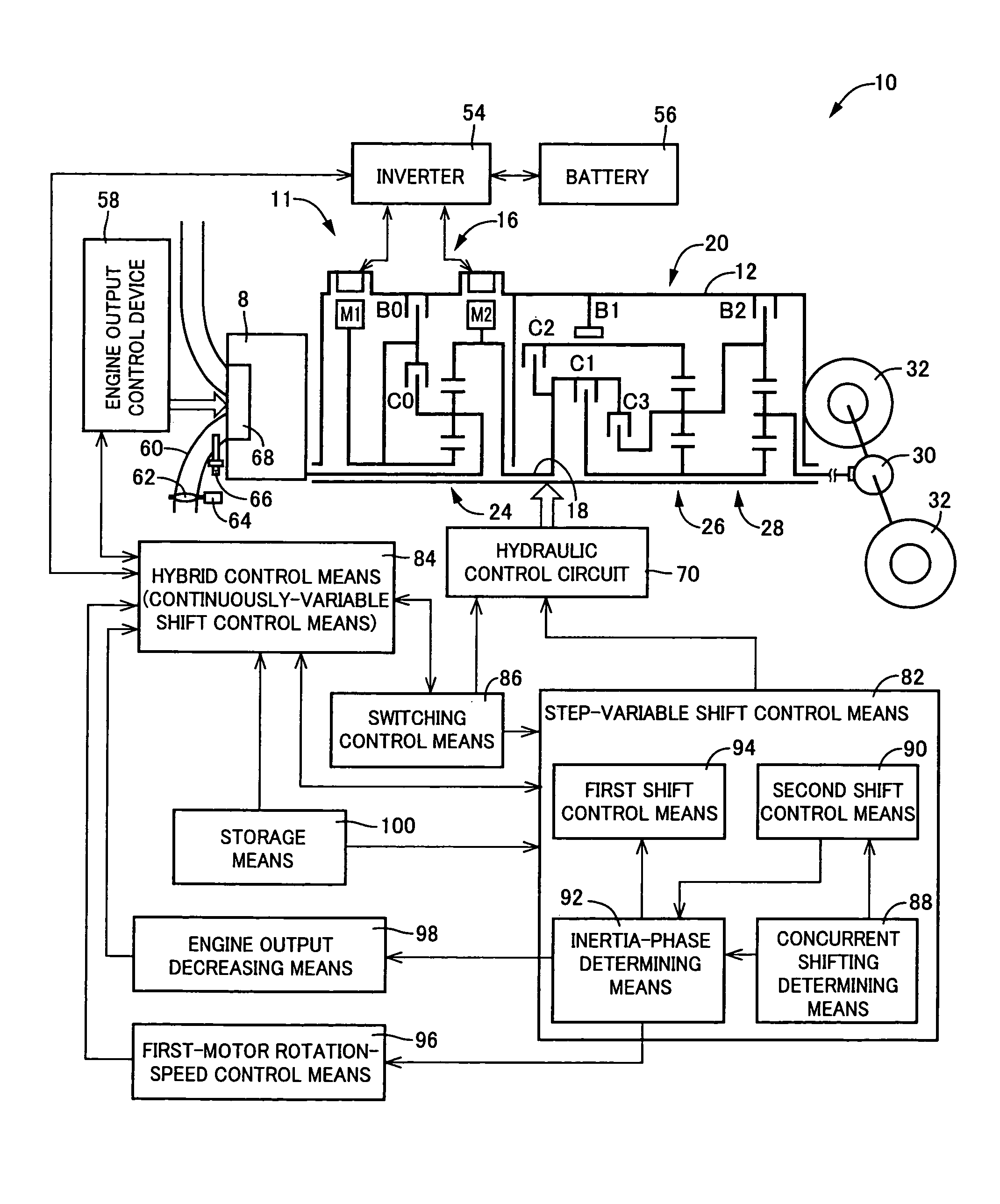
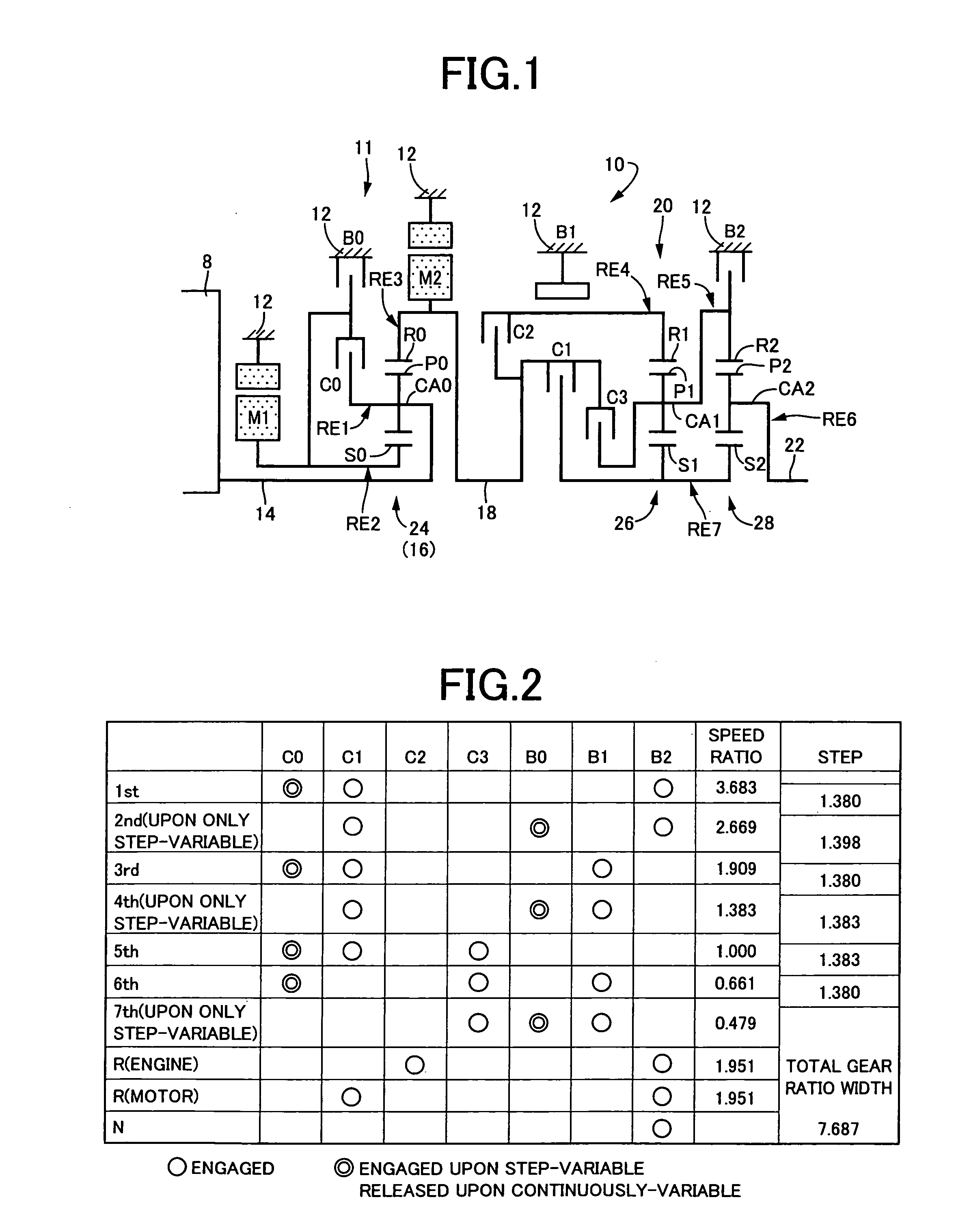
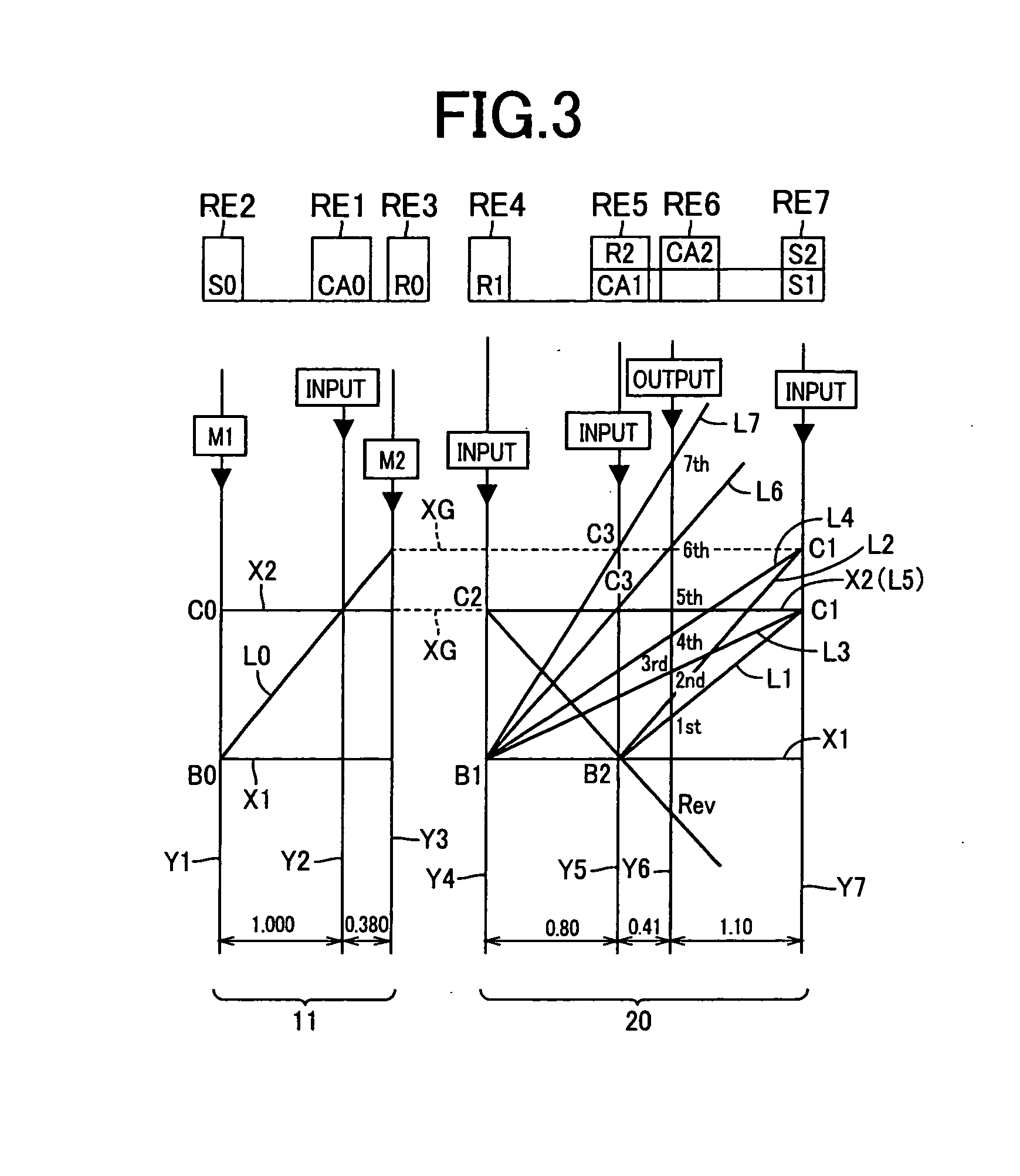
[0060]FIG. 1 is a skeleton view illustrating a shifting mechanism (power transfer device) 10 forming a part of a hybrid vehicle drive apparatus to which a control device of a first embodiment according to the present invention is applied. In FIG. 1, the shifting mechanism 10 includes: an input rotary member, i.e., an input shaft 14, mounted on a common axis in a transmission case (hereinafter referred to as a “case”) acting as a non-rotary member mounted on a vehicle body, which is connected directly to an engine 8 or indirectly connected thereto via a pulsation absorbing damper (vibration damping device), not shown; a differential portion 11 acting as a first shifting portion or a continuously-variable shifting portion connected to the input shaft 14; a second shifting portion, i.e., an automatic shifting portion 20 connected to a power transfer path in series via a power transfer member (power transfer shaft) 18 between the differential portion 11 and drive wheels 32 (see FIG. 7) ...

second embodiment

[0166]FIG. 11 is a skeleton view illustrating a structure of a shifting mechanism 110 of another embodiment according to the present invention. FIG. 12 is an engagement operation table representing the relationship between gear positions of a shifting mechanism 110 and a combination of engagements of hydraulically operated friction engaging devices. FIG. 13 is a collinear chart illustrating a shifting operation of the shifting mechanism 110.

[0167]Like the structure of the first embodiment, the shifting mechanism 110 includes the differential portion 11, composed of the first electric motor M1, the power distributing mechanism 16 and the second electric motor M2 disposed on a first axis RC1, and an automatic shifting portion114 of forward-drive four gear positions disposed on a second axis RC2 extending parallel to the first axis RC1. This is because of shortening an axial dimension in view of accommodating the shifting mechanism 110 in a trans-axle case (hereinafter referred to as a...


PUM


Abstract

The present invention provides a control device for a vehicular drive apparatus with a structure of enabling the suppression of gearshift shock occurring during concurrent shifting executed of a first shifting portion and a second shifting portion. When the concurrent shifting are executed around the same time in which a down shift in one of a differential portion (first shifting portion) and an automatic shifting portion (second shifting portion) and an upshift in the other of them are executed, a first electric motor is caused to control a rotation speed of a second rotary element (sun gear). Thus, a shifting progress state upon the concurrent shifting is controlled. This causes shifting directions i.e., variation of the engine rotation speed in shifting of a shifting mechanism to be set in a unidirectional, enabling the suppression of gearshift shock.

Description

TECHNICAL FIELD[0001]The present invention relates to a control device for a vehicular drive apparatus having a first shifting portion and a second shifting portion that are capable of performing step-variable shifting among a plurality of gear positions. More particularly, it relates to a technology of controlling a shifting progress state for concurrent shifting executed around the same time in which shifting in the first shifting portion and shifting in the second shifting portions are executed.BACKGROUND ART[0002]There has been known a vehicular drive apparatus including first shifting portion and second shifting portion that are capable of performing step-variable shifting among a plurality of gear positions. For instance, a drive apparatus for a hybrid vehicle, disclosed in Patent Publication 1, corresponds to such a vehicle drive apparatus.[0003]With such a vehicular drive apparatus disclosed in Patent Publication 1, a power transfer path, extending between an engine and driv...

Claims


Application Information

Patent Timeline
Patent Type & Authority Applications(United States)
IPC IPC(8): B60W20/00F16H59/68F16H59/38F16H61/08F16H61/686F16H61/684B60K6/547B60K6/543B60K6/445B60W10/10B60W10/06B60W10/08F02D29/02F16H61/68F16H63/50
CPCB60K1/02Y10T477/675B60K6/40B60K6/445B60K6/547B60W10/06B60W10/08B60W10/115B60W20/00B60W30/19F16H3/728F16H61/0437F16H2037/0873F16H2061/6603Y02T10/6239Y02T10/6286Y10T477/23B60K6/365B60L1/003B60L1/02B60L15/2054B60L2240/14B60L2240/26B60L2240/34B60L2240/36B60L2240/421B60L2240/423B60L2240/441B60L2240/443B60L2240/445B60L2240/461B60L2240/486B60L2250/16B60L2250/24B60L2250/26B60L2270/145Y02T10/72B60L50/61B60L50/16B60L58/12Y02T10/62Y02T10/64Y02T10/70Y02T10/7072B60W10/10B60W2510/0638B60W20/30
Inventor TABATA, ATSUSHIMATSUBARA, TOORUIWASE, YUJISHIBATA, HIROYUKI
Owner TOYOTA JIDOSHA KK
Why Eureka
Try Eureka