
Wideband tuner architecture

a receiver and wideband technology, applied in the field of wideband receiver systems and methods, can solve the problems of requiring a very expensive digital processing circuitry for a wide bandwidth of 800 mhz

Active Publication Date: 2013-09-03
ENTROPIC COMM INC
View PDF18 Cites 16 Cited by
  • Summary
  • Abstract
  • Description
  • Claims
  • Application Information

AI Technical Summary

Benefits of technology

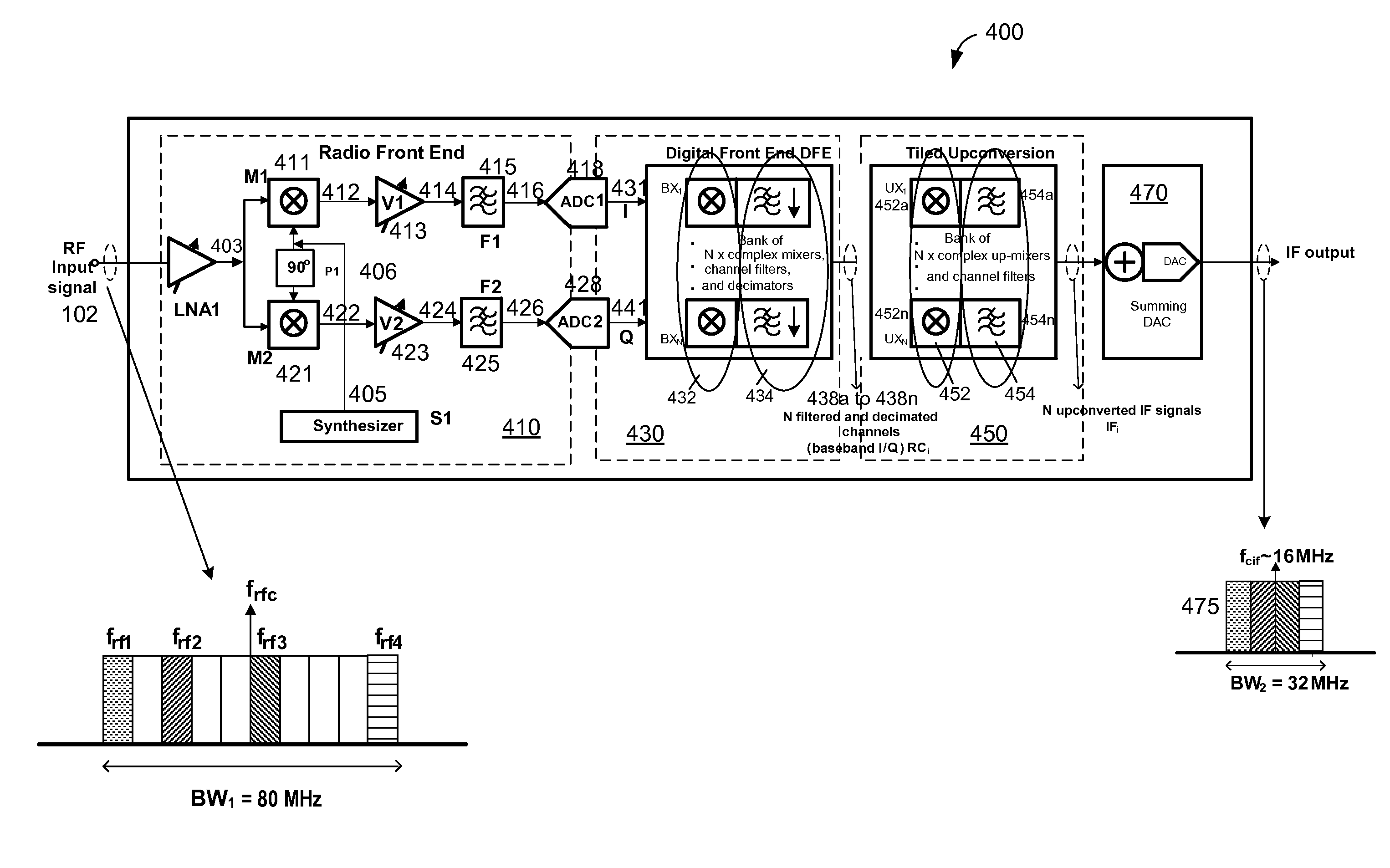
[0010]In certain embodiments of the present invention, the wideband receiver system additionally includes an up-converter module having multiple complex up-mixers, each of the complex up-mixers is configured to frequency up-shift each one of the desired RF channels to a sub-portion of an IF spectrum, wherein all sub-portions of the desired channels are adjacent to each another and form a contiguous frequency band in the IF spectrum. The act of frequency shifting the desired channels to the IF spectrum allows the wideband receiver system to directly interface with commercially available demodulators. Allowing the spacing of the desired channels in the contiguous spectrum to be variable allows a system to optimize placement of these desired channels for the purposes of avoiding sensitive portions of the spectrum which may either be vulnerable to spurious signals and interference; or which may generate interference directly or as a harmonic product, to other systems.

Problems solved by technology

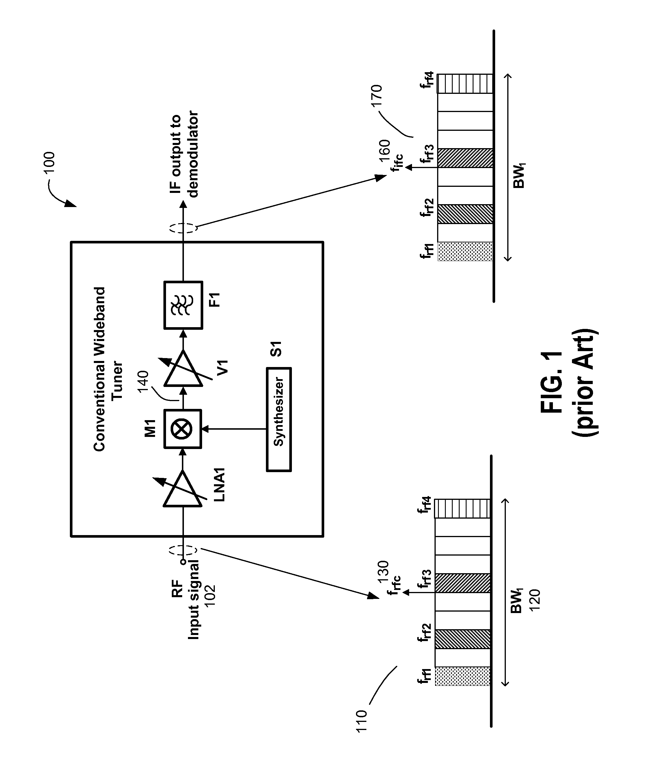
This wide bandwidth of 800 MHz would require a very expensive digital processing circuitry such as very high-speed analog to digital conversion and high-speed processor in the demodulator.

Method used


Image

  • Wideband tuner architecture
  • Wideband tuner architecture
  • Wideband tuner architecture

Examples


Embodiment Construction

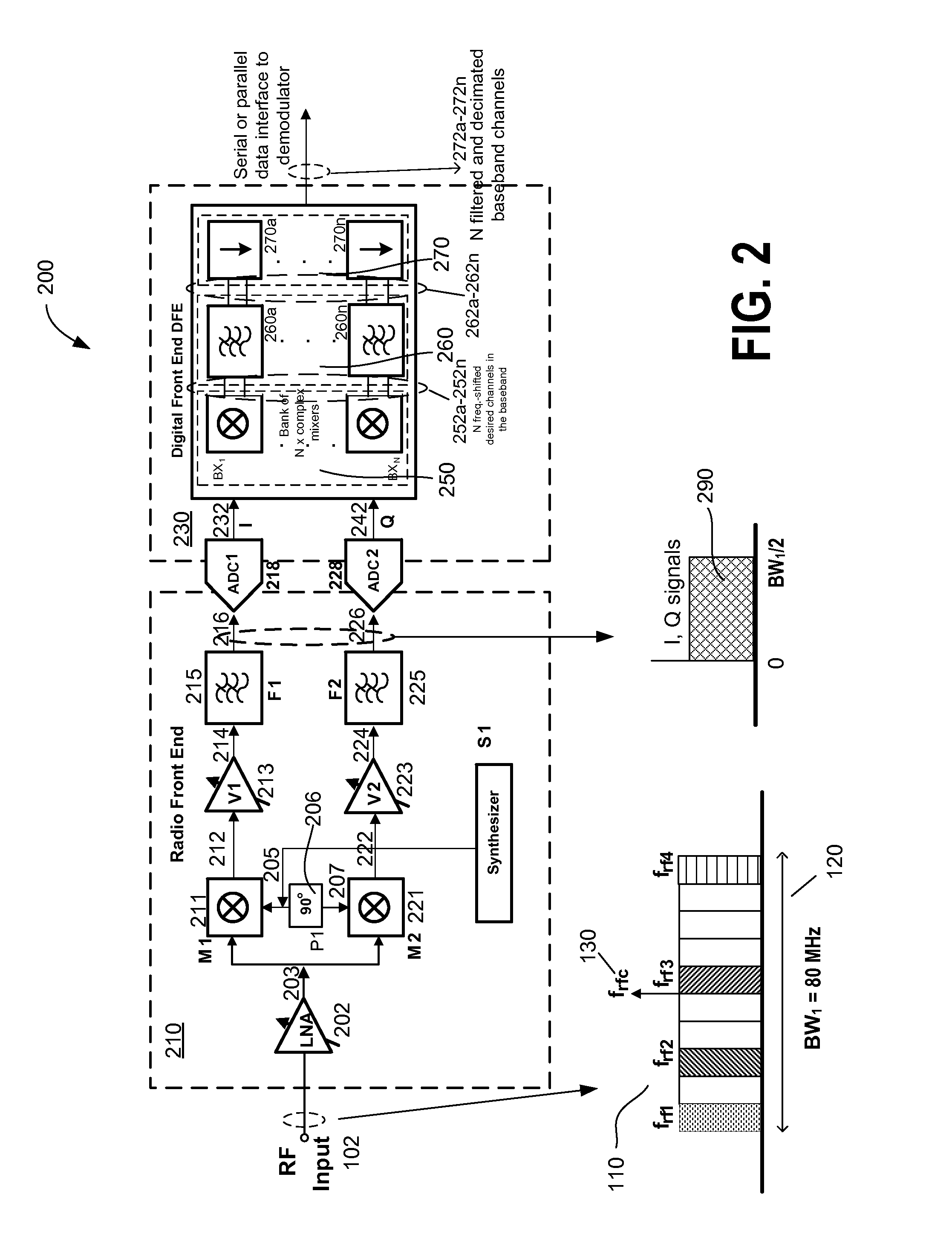
[0023]FIG. 2 is a schematic block diagram of a wideband receiver system 200 according to an embodiment of the present invention. Wideband receiver system 200 includes a radio front end 210 and a digital front end 230. Radio front end 210 may be a single very wide-band tuner receiver that captures the desired swath of channels located in non-contiguous portions of the spectrum having a frequency bandwidth BW1120. In this example, the number of available channels in BW1120 are assumed to be 10 with each channel occupying an 8 MHz bandwidth for a total of 80 MHz. Radio front end 210 is shown as including a low noise amplifier LNA 202 having an input terminal configured to receive an RF input signal 102. In the example shown, RF signal 102 includes four desired RF channels having the respective carrier frequency frf1, frf2, frf3, and frf4 that are located in non-contiguous portions of the wide frequency spectrum BW1. It is understood, however, that spectrum BW1120 may have any other num...


PUM


Abstract

A wideband receiver system is provided to concurrently receive multiple RF channels including a number of desired channels that are located in non-contiguous portions of a radio frequency spectrum and to group the number of desired channels into a contiguous frequency band. The system includes a wideband receiver having a complex mixer for down-shifting the multiple RF channels and transforming them to an in-phase signal and a quadrature signal in the baseband. The system further includes a wideband analog-to-digital converter module that digitizes the in-phase and quadrature signals and a digital frontend module that transforms the digital in-phase and quadrature signals to baseband signals that contains only the number of desired RF channels. that are now located in a contiguous frequency band. An up-converter module up-shifts the baseband signals to a contiguous band in an IF spectrum so that the system can directly interface with commercially available demodulators.

Description

CROSS-REFERENCES TO RELATED APPLICATIONS[0001]The present application claims benefit under 35 USC 119(e) of U.S. provisional application No. 61 / 170,526, filed Apr. 17, 2009, entitled “Wideband Tuner Architecture,” the content of which is incorporated herein by reference in its entirety.BACKGROUND OF THE INVENTION[0002]This invention relates to wideband receiver systems and methods having a wideband receiver that is capable of receiving multiple radio frequency channels located in a broad radio frequency spectrum. In particular, the invention relates to wideband receiver systems that are capable of receiving multiple desired television channels that extend over multiple non-contiguous portions of the broad frequency spectrum and grouping them into a contiguous, or substantially-contiguous frequency spectrum.[0003]Receivers used to down-convert and selectively filter TV channels are referred to as tuners, and tuners designed to concurrently receive several TV channels are referred to ...

Claims


Application Information

Patent Timeline
Patent Type & Authority Patents(United States)
IPC IPC(8): H04B1/16
CPCH04B1/0014H04N5/50H04N21/454H04N21/4383H04N21/4263H04N21/6193H04N21/6143H04N5/455H04N21/4382
Inventor REDDY, MADHUKARLING, CURTISGALLAGHER, TIM
Owner ENTROPIC COMM INC
Learn More