
Vehicle having a shift lever on a handlebar thereof

a technology of shift lever and handlebar, which is applied in the direction of switch power arrangement, basic electric elements, electric devices, etc., can solve the problems of reducing the likelihood of the vehicle stalling, difficult to reach, and reducing the driver's gripping force on the handl

Active Publication Date: 2011-08-30
BOMBARDIER RECREATIONAL PROD INC
View PDF17 Cites 15 Cited by
  • Summary
  • Abstract
  • Description
  • Claims
  • Application Information

AI Technical Summary

Benefits of technology

The present invention aims to improve the inconveniences of previous vehicles by providing a shifter and handlebar that are positioned near the driver's seat, with a switch on the handlebar that can be easily reached. The shifter and handlebar are positioned in a way that allows the driver to easily shift gears with their thumb. The invention also includes a housing with a switch on the rear side of the handlebar that can be easily reached. The shift lever is pivotally connected to the housing and is biased towards a rest position. The invention provides a more convenient and efficient vehicle design.

Problems solved by technology

This also greatly reduces the likelihood of the vehicle stalling because of a failed shifting attempt, which is common when vehicles equipped with manual transmissions are driven by inexperienced drivers.
If the shifter is not properly positioned, the shifter can be difficult to reach, which can lead to the driver's gripping force on the handle being reduced.
If these switches are not properly positioned on the housing, it can lead to some complicated finger gymnastics for a driver trying to actuate these switches without moving his hand too much on the handle.

Method used


Image

  • Vehicle having a shift lever on a handlebar thereof
  • Vehicle having a shift lever on a handlebar thereof
  • Vehicle having a shift lever on a handlebar thereof

Examples


Embodiment Construction

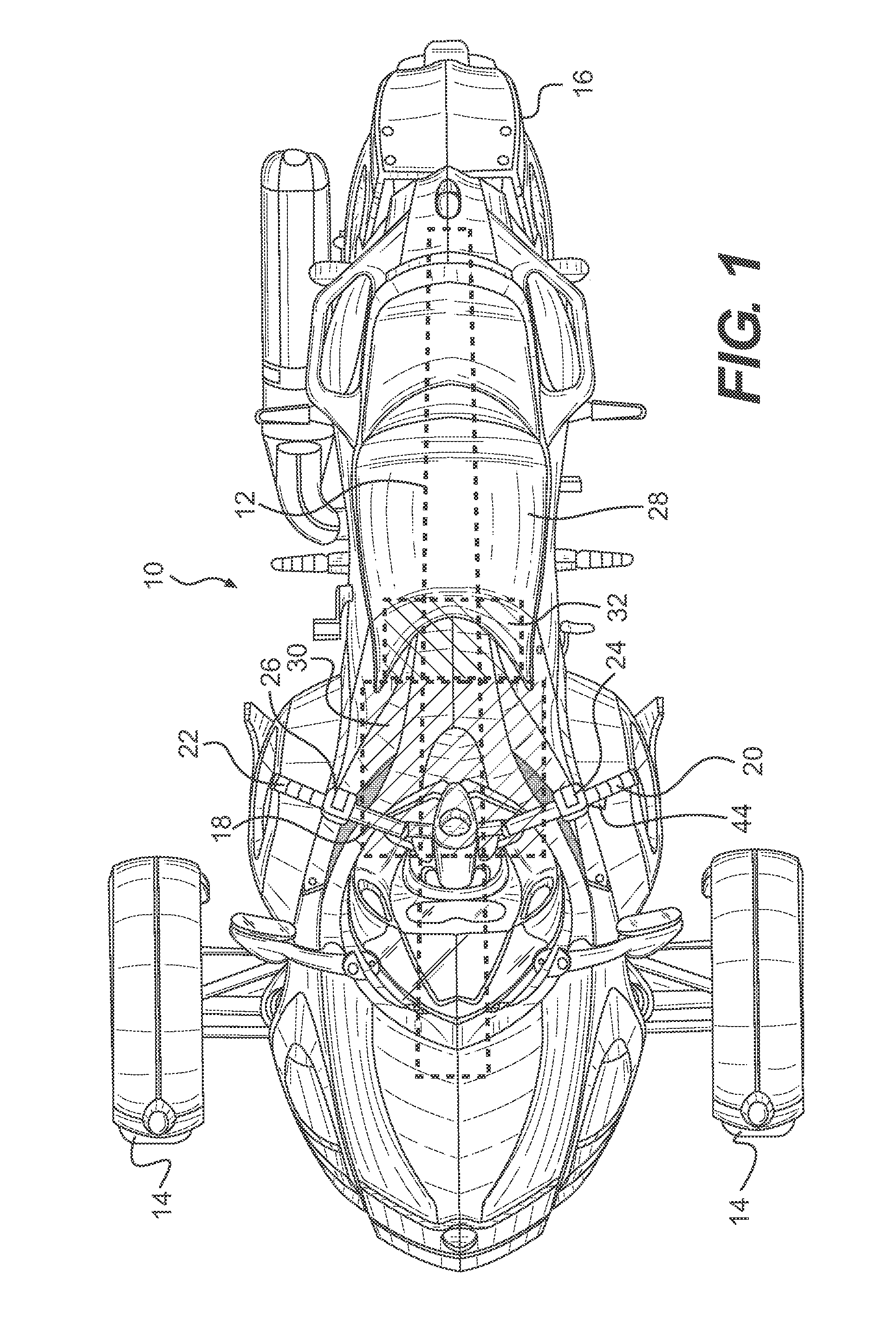
[0047]The present invention will be described with respect to a three-wheeled vehicle having a handlebar for steering. However it should be understood that the invention could be used in other wheeled vehicles having a handlebar for steering such as but, not limited to, a motorcycle, a scooter, and an all-terrain vehicle (ATV). U.S. Pat. No. 6,732,830, issued May 11, 2004, the entirety of which is incorporated herein by reference, describes the general features of an ATV.

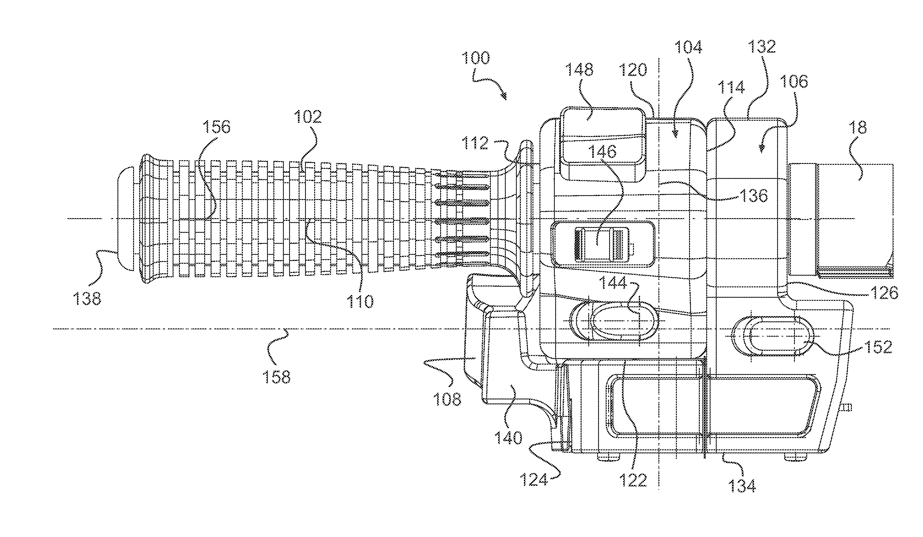
[0048]As shown in FIG. 1, a three-wheeled vehicle 10 has a frame 12 (shown schematically) to which two front wheels 14 and one rear wheel 16 are connected. A handlebar 18 is connected to the two front wheels 14 for steering the two front wheels 14. The handlebar 18 has a left handle 20 and a right handle 22 disposed at the ends of the handlebar 18. At least one left housing 24 and at least one right housing 26 are disposed adjacent their respective handles 20, 22. The handles 20, 22 and housings 24, 26 will be descr...


PUM


Abstract

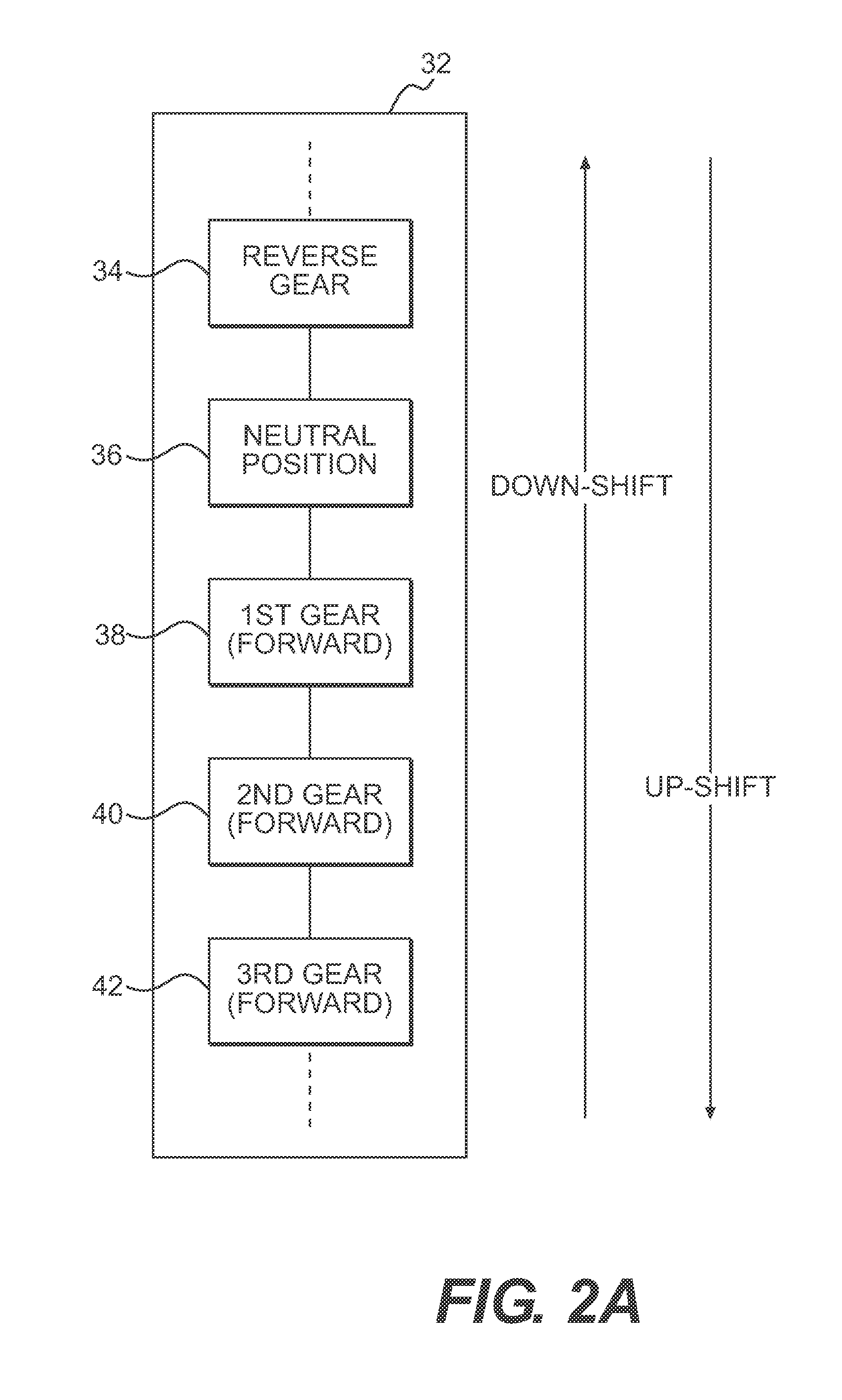
A vehicle (10) has a frame (12), at least two wheels (14, 16), a straddle seat (28), a handlebar (18) having first (20) and second (22) handles, an engine (30), a semi-automatic transmission (32), and a housing (24) disposed adjacent the first handle. A shift lever (108) is pivotally connected to the housing. At least a portion of the shift lever extends away from the handle side of the housing towards an end of the first handle and is disposed at least in part vertically below the first handle. The shift lever has rear (140) and front surfaces (142). The shift lever is movable to an up-shift position by pressing one of the front and rear surfaces, is movable to a down-shift position by pressing a remaining one of the front and rear surfaces, and is biased towards a rest position intermediate the up-shift and down-shift positions. The shift lever is operatively connected to the semi-automatic transmission.

Description

CROSS-REFERENCE[0001]The present application is the United States National Stage of PCT / US2008 / 062063, filed Apr. 30, 2008, entitled ‘Vehicle Having a Shift Lever on a Handlebar Thereof’, the entirety of which is incorporated herein by reference.FIELD OF THE INVENTION[0002]The present invention relates to a vehicle having a shift lever on a handlebar thereof. More specifically, the present invention relates to the positioning of the shift lever.BACKGROUND OF THE INVENTION[0003]Semi-automatic transmissions are being provided on many vehicles. With a semi-automatic transmission, the driver of the vehicle has control of the transmission by using a shifter with the advantage that the driver does not have to actuate a separate clutch actuator. When the driver actuates the shifter, a signal is sent to a control unit of the transmission which sends signals to cause a clutch connected to the transmission to disengage, to cause the transmission to shift gear once the clutch is disengaged, an...

Claims


Application Information

Patent Timeline
Patent Type & Authority Patents(United States)
IPC IPC(8): B60K20/06B60K23/02H01H9/06H01H3/22
CPCB62K5/027B62K5/05B62K11/14B62K23/06
Inventor PORTELANCE, MARTIN
Owner BOMBARDIER RECREATIONAL PROD INC
Learn More