Check patentability & draft patents in minutes with Patsnap Eureka AI!

Data communication system, data transmitting device, data transmitting method, data receiving device, and data receiving method

Active Publication Date: 2010-04-15
SONY CORP
View PDF6 Cites 18 Cited by
  • Summary
  • Abstract
  • Description
  • Claims
  • Application Information

AI Technical Summary

Benefits of technology

[0007]It is an object of the present invention to be able to ensure a real-time property while overcoming a packet loss in a radio environment.
[0011]In addition, on the transmitting side, the probe packet receiving section receives a probe packet. The predictive retransmission control section predicts a data packet lost on the receiving side among data packets sent from the data packet transmitting section to the first radio channel on a basis of a state of reception of the probe packet. For example, the predictive retransmission control section predicts that a data packet sent from the data packet transmitting section to the first radio channel during a period corresponding to a period of transmission of a probe packet not received by the probe packet receiving section is the lost data packet. Then, the predictive retransmission control section controls the data packet transmitting section so as to resend the data packet predicted to be lost to the first radio channel. In this case, the data packet transmitting section sends the data packet predicted to be lost on the receiving side to the first radio channel. As described above, the data communication system according to the present invention sends the data packet requested to be retransmitted and the data packet predicted to be lost on the receiving side from the data packet transmitting section to the first radio channel, so that a packet loss on the receiving side can be overcome. In addition, the data communication system predicts the data packet lost on the receiving side on the basis of a state of reception of the probe packet, and sends the data packet from the data packet transmitting section to the first radio channel without waiting for a retransmission request from the receiving side, so that a real-time property on the receiving side can be ensured.
[0017]As described above, the retransmission request signal for requesting retransmission of the predetermined data packet necessary for the decoder to obtain the received data is sent to the second radio channel, and the probe packet is sent to the second radio channel at fixed intervals. Thus, as described above, on the transmitting side, the data packet requested to be retransmitted and the data packet predicted to be lost on the receiving side can be sent from the data packet transmitting section to the first radio channel, so that a packet loss on the receiving side can be overcome. In addition, on the transmitting side, the data packet lost on the receiving side is predicted on the basis of the state of reception of the probe packet, and the data packet can be sent from the data packet transmitting section to the first radio channel without waiting for a retransmission request from the receiving side, so that a real-time property on the receiving side can be ensured.
[0018]According to the present invention as described above, the probe packet is transmitted from the receiving side to the transmitting side at fixed intervals, and the transmitting side predicts a data packet lost on the receiving side and retransmits the data packet to the receiving side according to the state of reception of the probe packet. It is thus possible to favorably ensure a real-time property while overcoming a packet loss in a radio environment.

Problems solved by technology

However, in a radio environment in which many packet losses are burst losses, there is a problem in that the effect of FEC is reduced and therefore the FEC / ARQ combination system does not function effectively.
Moreover, because retransmission requests by ARQ to compensate therefor are made en bloc after an end of a burst loss, retransmitted packets may not arrive within an allowable delay.

Method used


Image

  • Data communication system, data transmitting device, data transmitting method, data receiving device, and data receiving method
  • Data communication system, data transmitting device, data transmitting method, data receiving device, and data receiving method
  • Data communication system, data transmitting device, data transmitting method, data receiving device, and data receiving method

Examples


Embodiment Construction

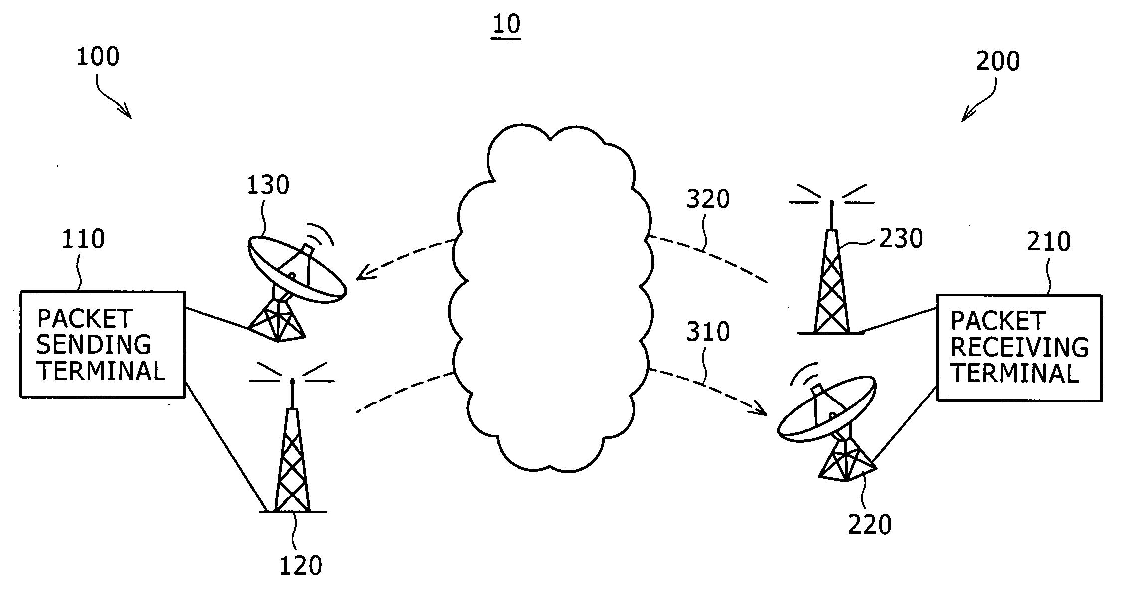
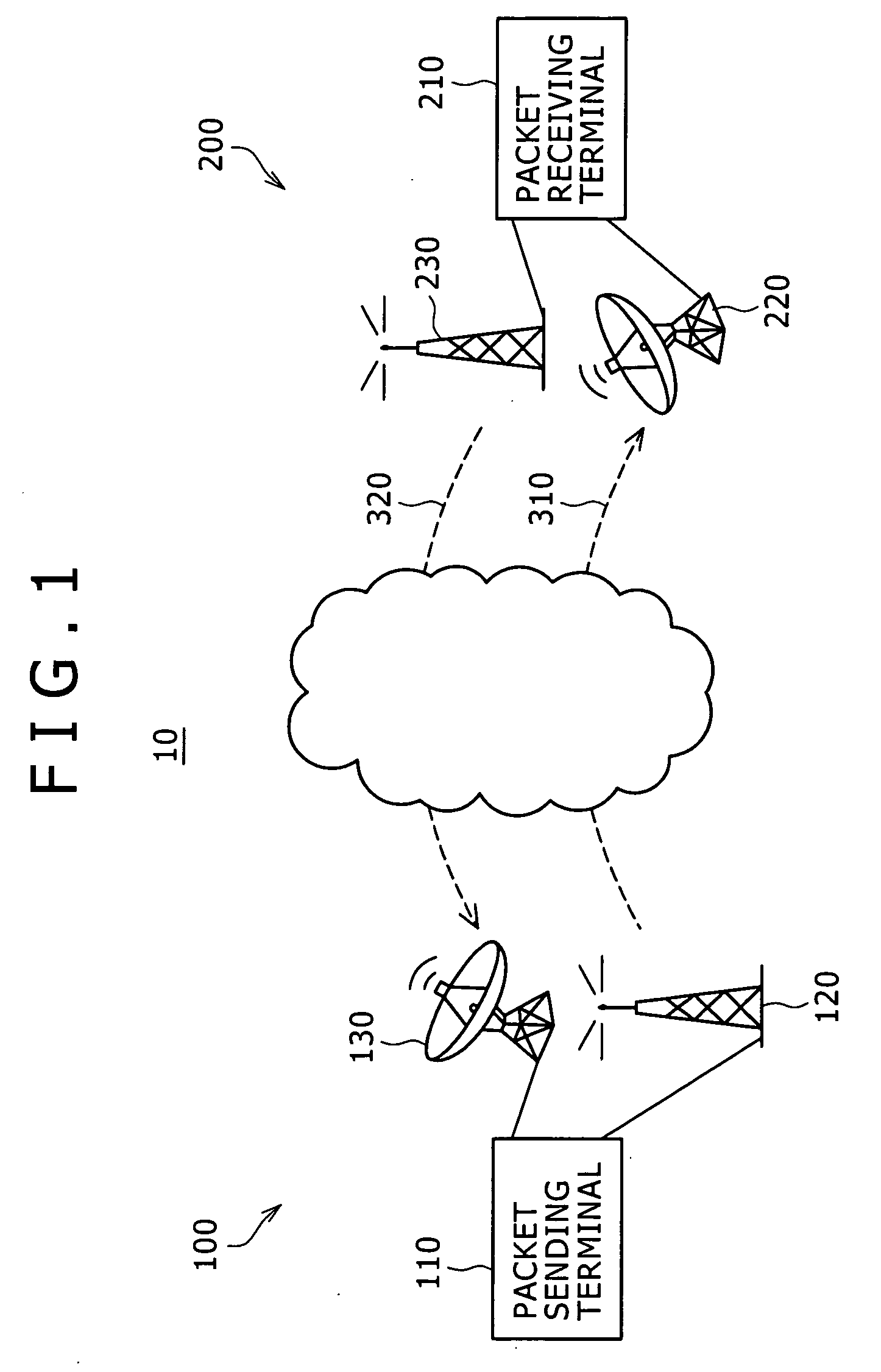
[0028]FIG. 1 shows a configuration of a data communication system 10 as an embodiment. This data communication system 10 has a data transmitting device 100 and a data receiving device 200. The data transmitting device 100 includes a packet sending terminal 110, a radio transmitting terminal 120, and a radio receiving terminal 130. The data receiving device 200 includes a packet receiving terminal 210, a radio receiving terminal 220, and a radio transmitting terminal 230.

[0029]A data packet transferred from the packet sending terminal 110 of the data transmitting device 100 to the radio transmitting terminal 120 is received by the radio receiving terminal 220 of the data receiving device 200 by using a first radio channel 310. In addition, the packet receiving terminal 210 of the data receiving device 200 sends a probe packet to a second radio channel 320 through the radio transmitting terminal 230. The packet sending terminal 110 of the data transmitting device 100 receives the prob...


PUM


Abstract

A probe transmitting section (216) in a packet receiving terminal (210) sends a probe packet to a second radio channel (320) at fixed intervals. A probe analyzing section (117) in a packet sending terminal (110) detects a burst loss on the basis of a state of reception of the probe packet. When a burst loss detection is detected, a predictive retransmission control section (118) predicts that a data packet transmitted during the period of the detected burst loss among data packets sent from a priority processing transmission buffer (115) to a first radio channel (310) is a data packet lost on a receiving side, reads the data packet from a retransmission buffer (114), and then sends the data packet to the priority processing transmission buffer (115). A real-time property can be ensured while a packet loss is overcome in a radio environment.

Description

TECHNICAL FIELD[0001]The present invention relates to a data communication system for transmitting a data packet from a transmitting side to a receiving side using a radio channel, a data transmitting device, a data transmitting method, a data receiving device, and a data receiving method. The present invention relates particularly to a data communication system and the like that can ensure a real-time property while overcoming a packet loss in a radio environment by transmitting a probe packet from a receiving side to a transmitting side at fixed intervals, and predicting a data packet lost on the receiving side on the basis of a state of reception of the probe packet and retransmitting the data packet to the receiving side on the transmitting side.[0002]The present application claims priority on the basis of Japanese Patent Application No. 2006-242187 filed on Sep. 6, 2006 in Japan, which application is cited to the present application by reference.BACKGROUND ART[0003]The spread o...

Claims


Application Information

Patent Timeline
IPC IPC(8): H04J3/24H04L1/16H04L29/02H04L29/06H04L29/08H04W24/06H04W28/00H04W28/04
CPCH04L1/1657H04L1/1887H04L1/1854H04L1/1812H04L1/18
Inventor ITAKURA, EISABUROSUNAHARA, SEITAKAHASHI, YUTAKAKASAHARA, SHOJIMASUYAMA, HIROYUKIUCHIDA, YUSUKE
Owner SONY CORP
Features
  • R&D
  • Intellectual Property
  • Life Sciences
  • Materials
  • Tech Scout
  • Unparalleled Data Quality
  • Higher Quality Content
  • 60% Fewer Hallucinations
Learn More