Forceps for gripping and transporting small objects, usable in particular in dental surgery

Inactive Publication Date: 2010-04-15
WAM SPA
View PDF14 Cites 14 Cited by
  • Summary
  • Abstract
  • Description
  • Claims
  • Application Information

AI Technical Summary

Benefits of technology

[0007]Forceps are known, moreover, the jaws of which are fitted with flexible cushions (DE 10 2004 017 402, U.S. Pat. No. 3,898,738, U.S. Pat. No. 5,044,954, U.S. Pat. No. 3,834,026, WO 01/66031, US 2006/0127835). Forceps are also known, in which the closing together of the jaws into the gripping position takes place automatically under the effect of the elasticity of the arms (DE 10 2004 017 402, U.S. Pat. No. 4,035,919). However, none of the devices described in the documents abo

Problems solved by technology

The major drawback shared by all of these devices is the rigidity of their jaws, as a result of which there are normally only small contact areas or few points of contact between the jaws and the object grasped, so that the grip on the object is unsafe in many cases, and there is a risk that the object will therefore escape the jaws of the forceps unexpectedly and fall inopportunely during handling.
However, none of the devices described in the documents above, applicab

Method used


Image

  • Forceps for gripping and transporting small objects, usable in particular in dental surgery
  • Forceps for gripping and transporting small objects, usable in particular in dental surgery
  • Forceps for gripping and transporting small objects, usable in particular in dental surgery

Examples


Embodiment Construction

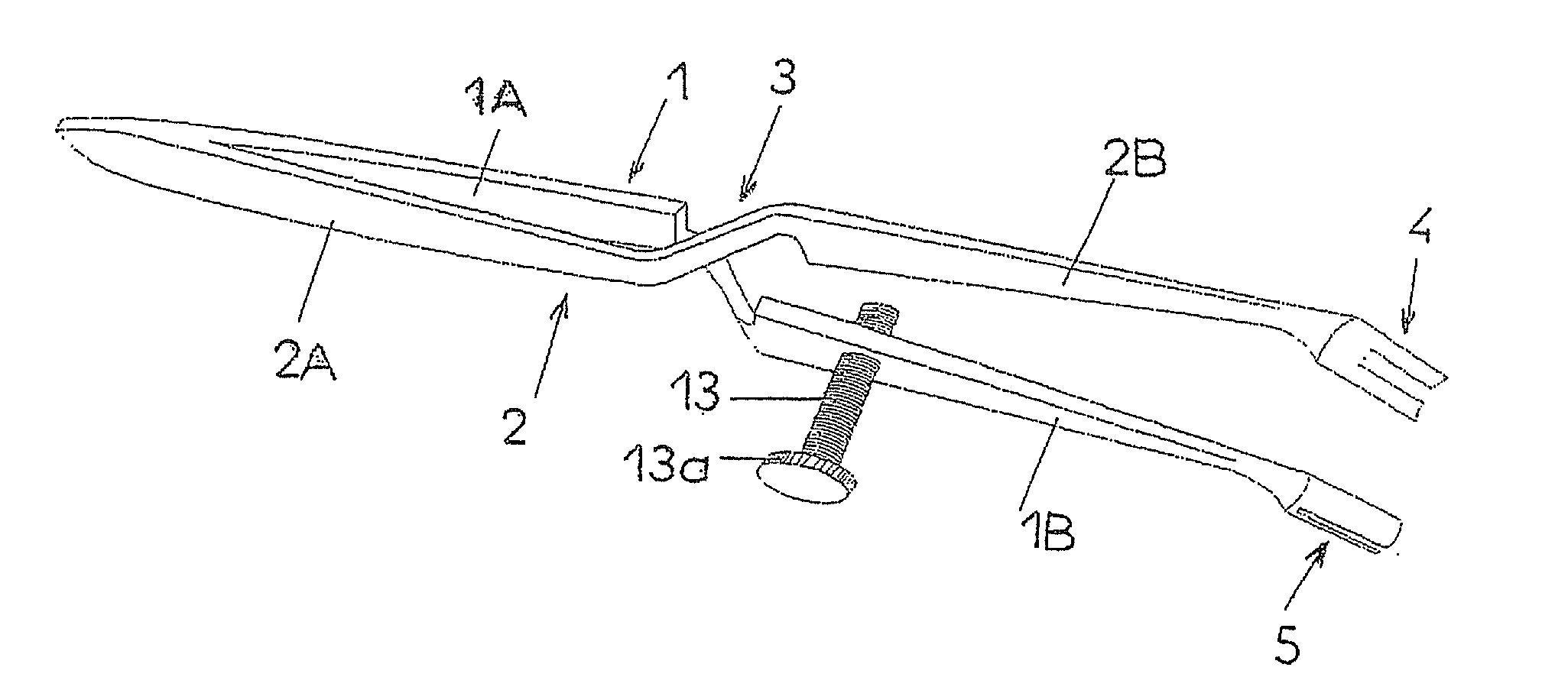
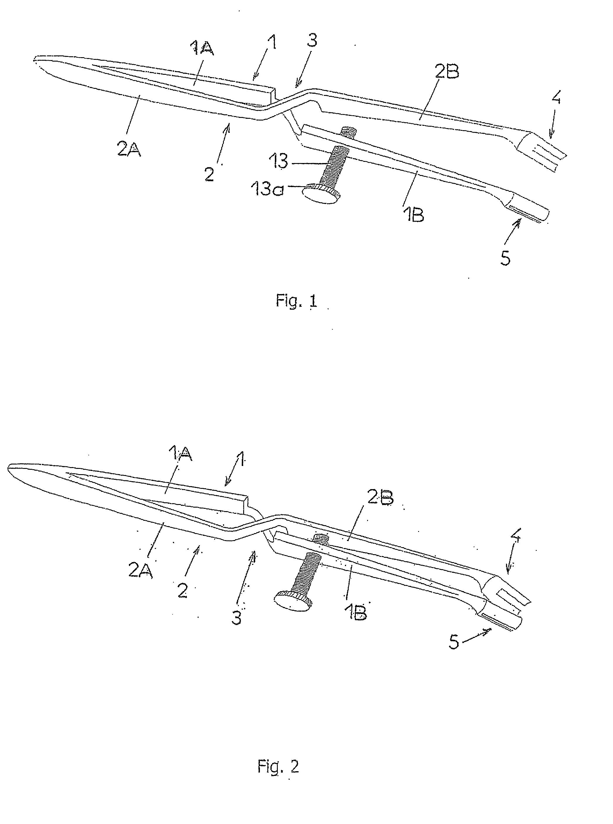
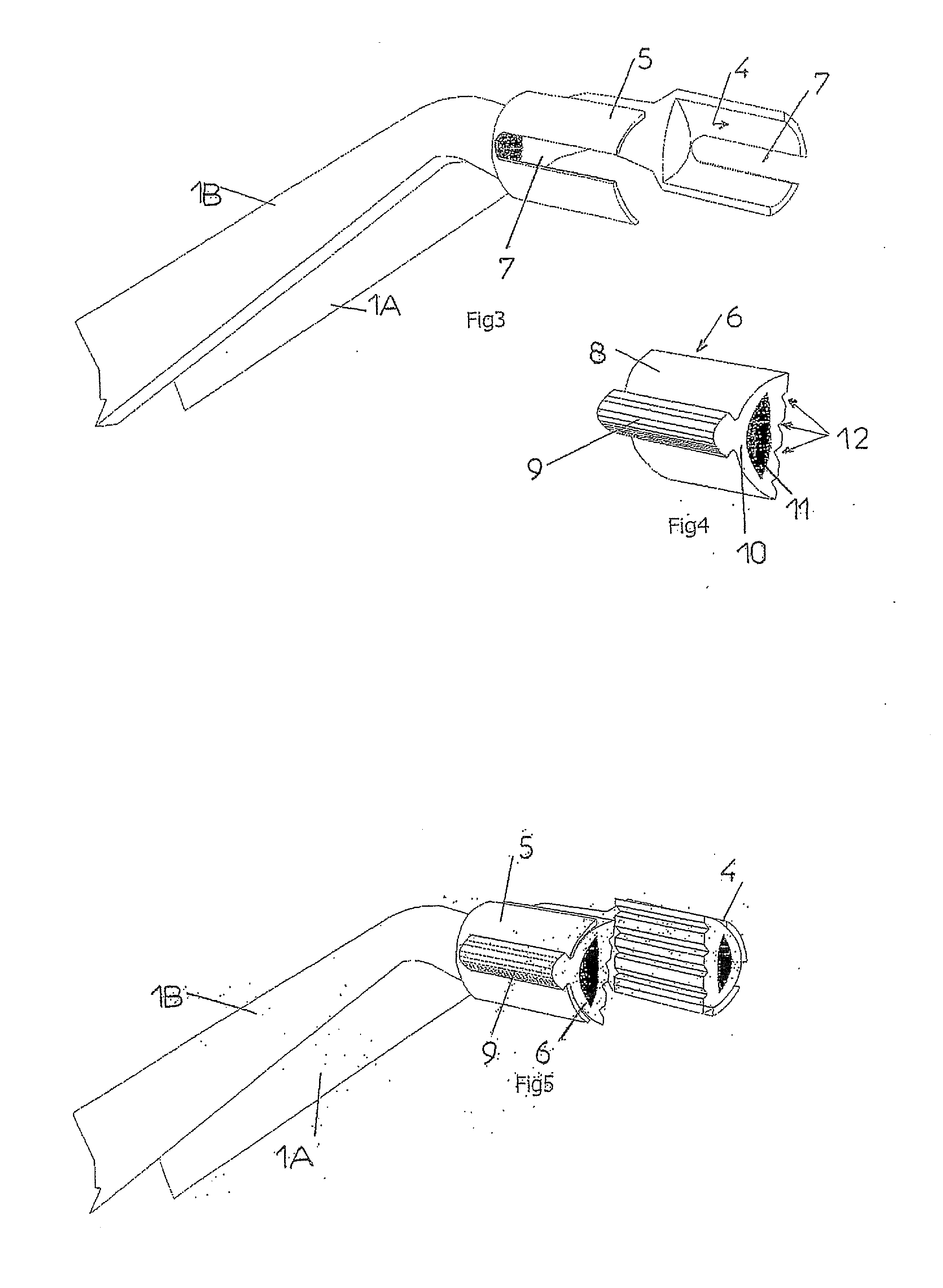
[0021]Reference will be made to the said drawings in order to describe an example of an advantageous, but in no way limitative, embodiment of the forceps or tweezers according to the invention. In the following description, the expression “flexible material” denotes a material preferably but non-limitatively having a degree of hardness allowing for its deformation by at least one millimetre when a pressure of less than 5 N is applied to it for a contact area of 50 mm2.

[0022]According to FIGS. 1 and 2, the forceps shown are self-locking tweezers of the type made up of two arms 1 and 2, intersecting freely at their intermediate part 3 and comprising a proximal manoeuvring part or handle 1A, 2A and a distal gripping part 1B, 2B, extending on either side of their intersection zone 3. The arms 1 and 2 are essentially made from a metal having the ability to be flexible. The proximal parts 1A, 2A are elastically joined at one of their ends and spread apart progressively towards the interse...


PUM


Abstract

Self-locking forceps for gripping and transporting small objects and usable in particular in dental surgery, said forceps comprising two branches that intersect freely and have a proximal manoeuvring part and a distal gripping part, the proximal parts being joined elastically at one of their ends, while the distal parts end in jaws, such that the closing together of the proximal parts or grips causes the distal parts to spread apart, while release of the pressure exerted on said proximal parts is translated into an automatic closing together of the distal parts and therefore of the jaws in a clamping position; at least one of said jaws is provided with a cushion of flexible material; said self-locking forceps being provided with a means for limiting the clamping force generated by the return force of the spring formed by the proximal parts of the forceps.

Description

CROSS-REFERENCE TO RELATED APPLICATIONS[0001]This application is a National Phase Entry of International Application No. PCT / FR2007 / 001643, filed Oct. 9, 2007, which claims priority to French Patent Application No. 0609008, filed Oct. 13, 2006, both of which are incorporated herein by reference.BACKGROUND AND SUMMARY[0002]The present invention relates to forceps for gripping and transporting small objects, usable in particular in dental surgery. In the aforementioned advantageous application, these forceps can be used in particular to grasp, transport to the insertion site and insert, at the site, dental prosthesis parts of various shapes and sizes such as, for example, crowns, bridges, implants, inlays, etc.[0003]The following are currently used for such handling:[0004]self-locking forceps with curved or straight metal jaws;[0005]self-locking forceps with diamond-coated metal jaws;[0006]self-locking tweezers, the two jaws of which are each fitted with a pad of a ribbed rigid rubber...

Claims


Application Information

Patent Timeline
IPC IPC(8): A61C3/16
CPCA61B17/30A61C13/12A61C7/146A61C7/04
Inventor MULLER, ALEXANDREMULLER, WLLIAM
Owner WAM SPA
Why Eureka
Try Eureka