Riding Mower Ramp

a mower and ramp technology, applied in the field of ramps, can solve the problems of difficult to access the underside portion of the machine, difficult to turn the machine over to access the underside portion, and often overkill for the operator, so as to achieve the effect of ease of use and safety

Inactive Publication Date: 2010-04-22
HOPKINS MFG
View PDF19 Cites 5 Cited by
  • Summary
  • Abstract
  • Description
  • Claims
  • Application Information

AI Technical Summary

Benefits of technology

[0008]As the ramp rocks about a fixed pivot point from the ready position to the support position, the shifting of the body from the first substantially planar surface to the second substantially planar surface provides clear feedback to an operator of the vehicle that the wheel is supported on the ramp in a stable support position. The feedback provided by the shifting of the body between discrete positions allows the operator to eliminate the guesswork or need for a spotter associated with traditional ramps. The rocking feedback feature provides ease of use and safety to the operator using the ramp.

Problems solved by technology

With such machinery, it can be difficult to access the underneath portion of the machine (as may be required to change the oil or check the blade) when the machine is right side up and on the ground.
Turning the machine over to access the underneath portion is often undesirable for various reasons, such as difficulty in moving a heavy machine and / or the desire to prevent liquids from spilling.
While each of these devices are satisfactory in some respects, each also presents drawbacks.
A lift is very expensive and is often overkill for an operator that only needs to raise the machine off the ground a small distance.
Those of ordinary skill in the art will also appreciate that a drive-on jack or ramp can be used to lift a vehicle wheel, but such conventional jacks or ramps have curved ground-engaging surfaces that make it difficult for an operator to determine when the vehicle is properly supported in a stable position on the jack or ramp.

Method used


Image

  • Riding Mower Ramp
  • Riding Mower Ramp
  • Riding Mower Ramp

Examples


Embodiment Construction

[0023]The present invention is susceptible of embodiment in many different forms. While the drawings illustrate, and the specification describes, certain preferred embodiments of the invention, it is to be understood that such disclosure is by way of example only. There is no intent to limit the principles of the present invention to the particular disclosed embodiments.

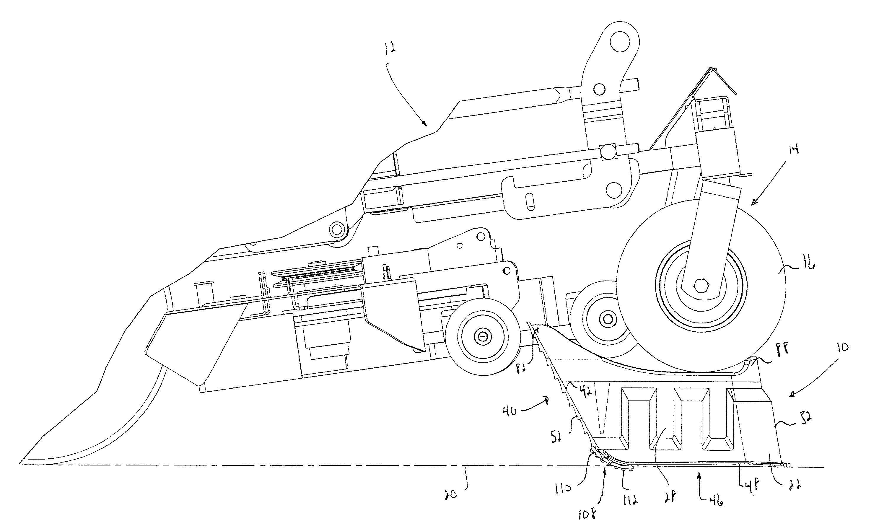
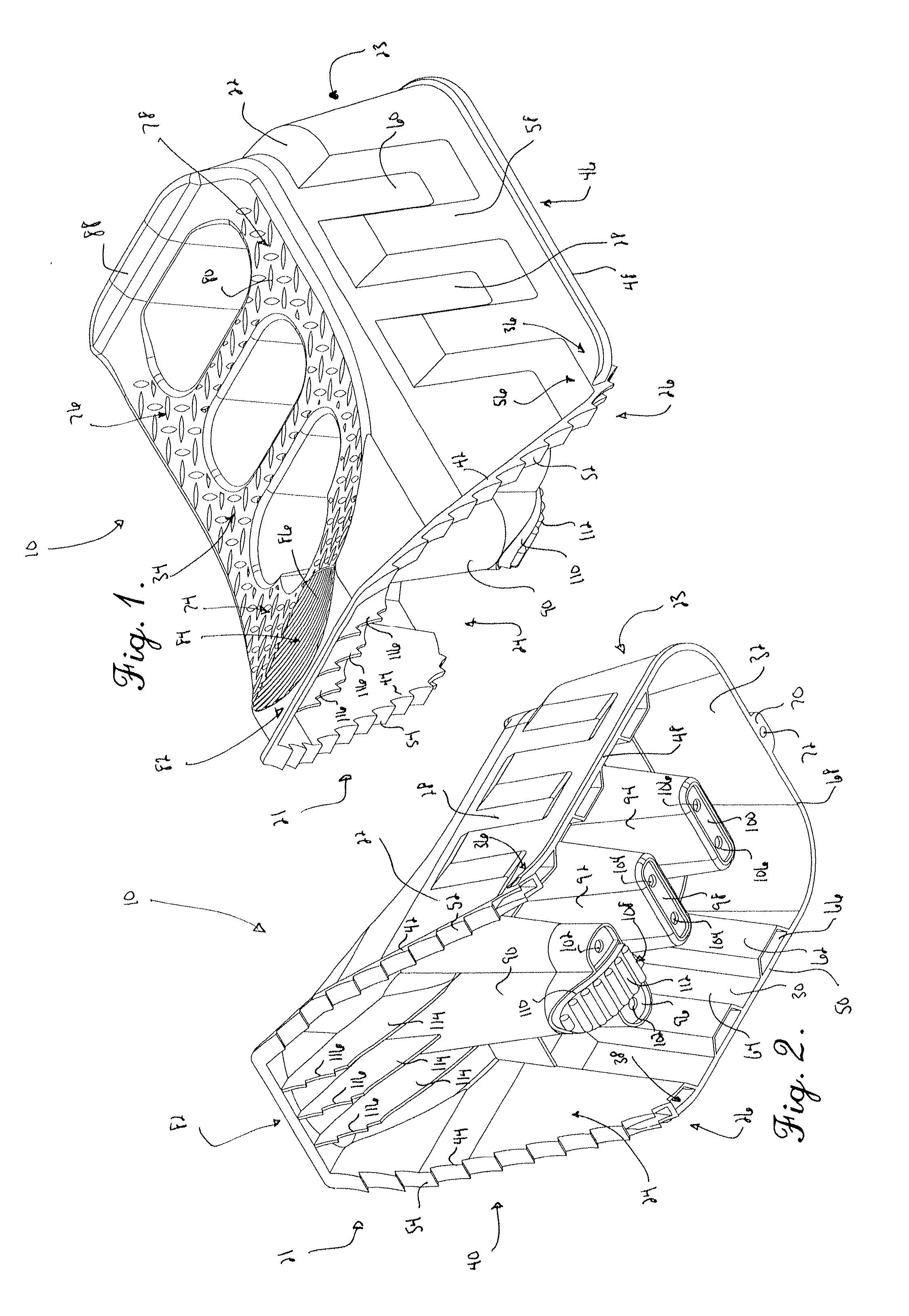
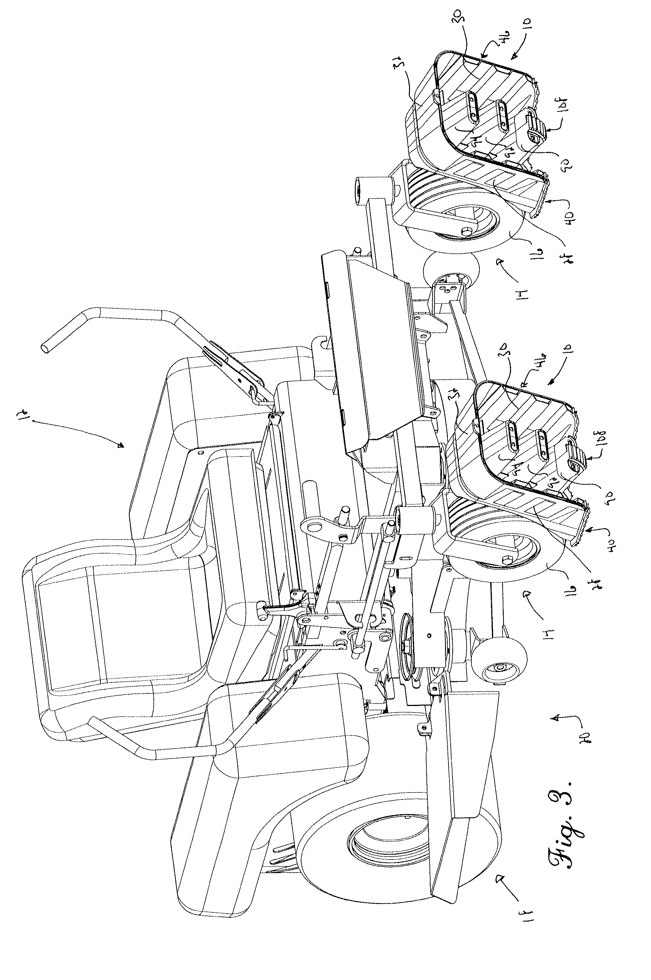
[0024]With initial reference to FIGS. 1 and 2, a ramp 10 constructed in accordance with a preferred embodiment of the present invention is configured to lift and support a wheel of a vehicle as such a wheel is driven onto the ramp 10. Turning briefly to FIG. 3, a vehicle in the form of a mower 12 is depicted in association with a pair of ramps 10. As will be readily appreciated by one of ordinary skill in the art, the mower 12 depicted in FIG. 3 is illustrated by way of example only as one possible vehicle that can be used in conjunction with the ramp 10 for lifting and supporting of the same. The ramp 10 could alter...


PUM


Abstract

A ramp is provided for lifting and supporting a wheel of a vehicle thereon when the wheel is driven onto the ramp. The ramp includes a body that is shiftable between a ready position and a discrete support position and presents a ground-engaging surface including a first portion that engages the ground in the ready position and a second portion that engages the ground in the support position. The first and second surface portions are substantially planar and define an angle therebetween through which the body rocks about a fixed pivot as a wheel moving along a wheel-engaging surface causes the body to move from the ready position to the support position. A pair of ramps is provided for lifting and supporting a pair of wheels, with the ramps being nestable for compact storage.

Description

CROSS-REFERENCE TO RELATED APPLICATIONS[0001]This application is a continuation-in-part of U.S. Design patent application Ser. No. 29 / 326,559, entitled RIDING MOWER RAMP, filed Oct. 20, 2008, which is hereby incorporated by reference herein.BACKGROUND OF THE INVENTION[0002]1. Field of the Invention[0003]The present invention relates generally to a ramp for use in raising and supporting a wheel of a riding mower or similar machine for maintenance purposes. More specifically, the present invention concerns a ramp that includes substantially planar ground-engaging surface portions that define a ready position and a support position, with the ramp being configured to rock over center from one position to the other in response to the wheel being driven along a wheel-engaging surface.[0004]2. Discussion of the Prior Art[0005]Those of ordinary skill in the art will appreciate that riding mowers and similar machines require occasional maintenance. With such machinery, it can be difficult to...

Claims


Application Information

Patent Timeline
Patent Type & Authority Applications(United States)
IPC IPC(8): B66F7/24
CPCB66F7/243
Inventor FICK, ORVAL LEEFORBIS, CHARLIE L.
Owner HOPKINS MFG
Why Eureka
Try Eureka