
Projection System Using High-Frequency Drive Modulation to Reduce Perceived Speckle

a projection system and high-frequency drive technology, applied in the field of optical projection systems, can solve the problems of unmatched image quality of laser-based projection systems, easy modulation of laser diodes to form complex images, and image artifacts known as “speckles"

Inactive Publication Date: 2010-04-22
MICROVISION
View PDF3 Cites 29 Cited by
  • Summary
  • Abstract
  • Description
  • Claims
  • Application Information

AI Technical Summary

Benefits of technology

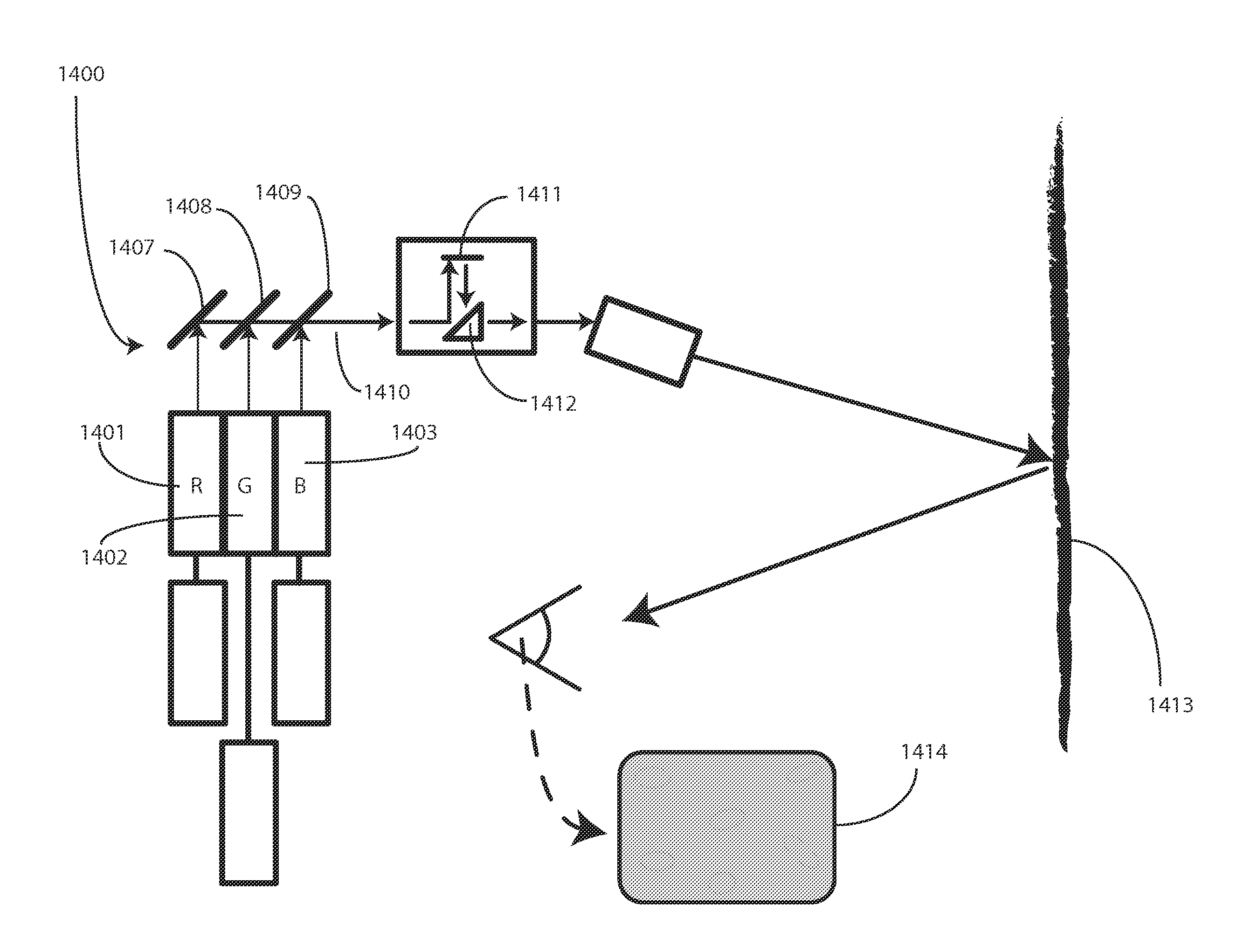
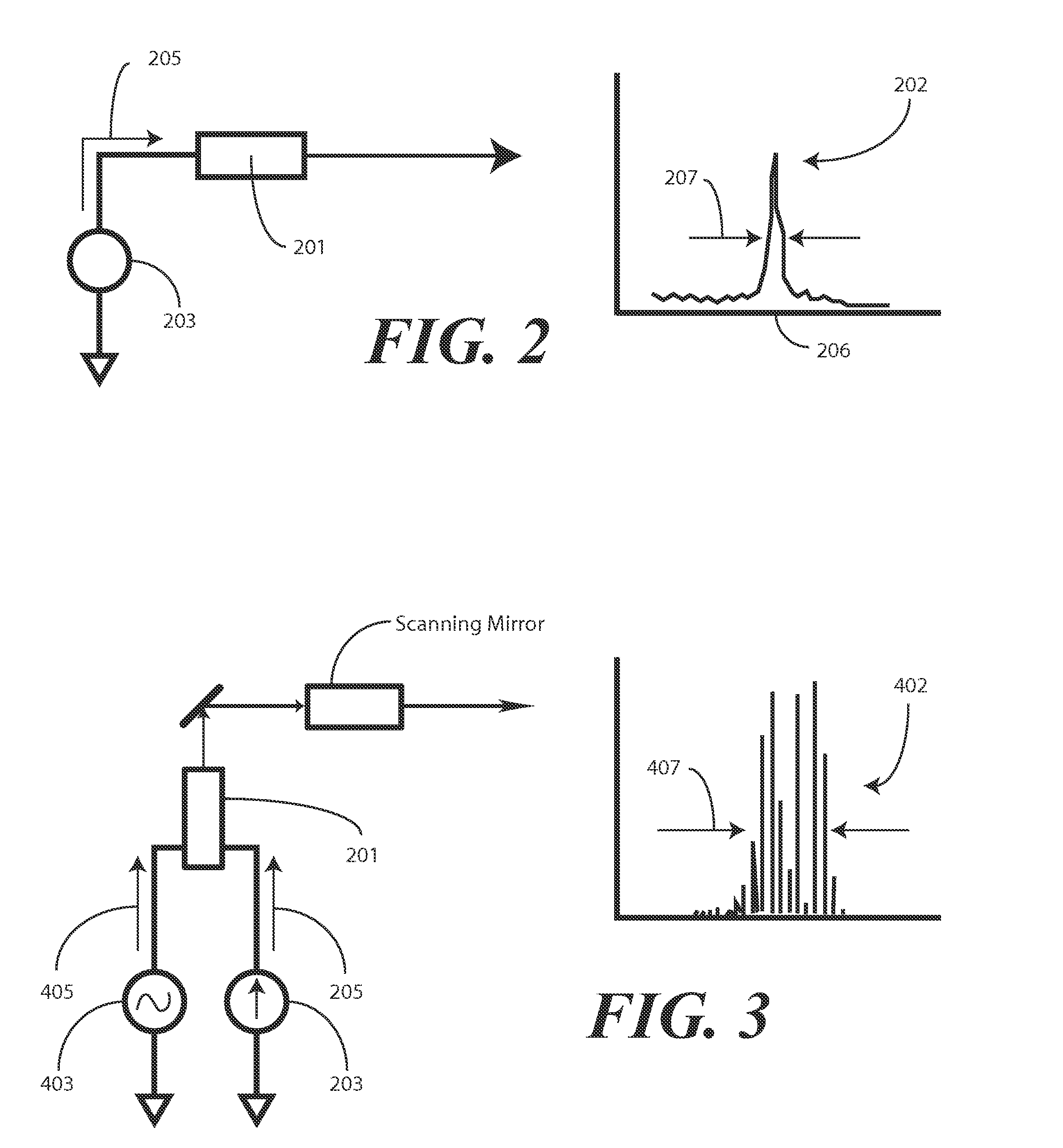
The patent text describes a new system for reducing speckle in laser-based projection systems. Speckle is a visual artifact caused by the coherent light sources used in these systems. The new system uses a high-frequency AC drive signal to induce a controlled chaos in selected lasers, which broaden the spectral width of the lasers and reduce speckle as perceived by the viewer. The invention is simpler and less expensive than previous speckle reduction systems and does not add significant complexity to the overall system design. The technical effect of the invention is to improve the quality of images produced using laser-based projection systems.

Problems solved by technology

The image quality associated with laser-based projection systems is unmatched by systems using conventional projection devices.
Further, the light from laser diodes is easily modulated to form complex images.
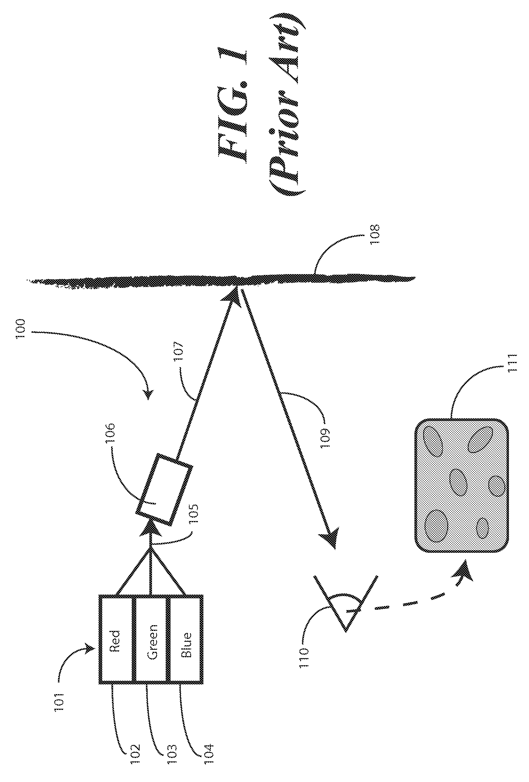
One practical drawback associated with using lasers in projection systems is the image artifact known as “speckle.” Speckle occurs when a coherent light source is projected onto an imperfect projection medium.
The presence of speckle often tends to perceptibly degrade the quality of the image produced using the laser projection system.
A drawback associated with each of these systems is that they add substantial cost and complexity to the overall system design.
For instance, time-varying diffusers require parts that adversely affect the overall system size and complexity.

Method used


Image

  • Projection System Using High-Frequency Drive Modulation to Reduce Perceived Speckle
  • Projection System Using High-Frequency Drive Modulation to Reduce Perceived Speckle
  • Projection System Using High-Frequency Drive Modulation to Reduce Perceived Speckle

Examples


Embodiment Construction

[0027]Before describing in detail embodiments that are in accordance with the present invention, it should be observed that the embodiments reside primarily in combinations of method steps and apparatus components related to an imaging system configured to reduce perceived speckle. Accordingly, the apparatus components and method steps have been represented where appropriate by conventional symbols in the drawings, showing only those specific details that are pertinent to understanding the embodiments of the present invention so as not to obscure the disclosure with details that will be readily apparent to those of ordinary skill in the art having the benefit of the description herein.

[0028]It will be appreciated that embodiments of the invention described herein may be comprised of one or more conventional processors and unique stored program instructions that control the one or more processors to implement, in conjunction with certain non-processor circuits, some, most, or all of ...


PUM


Abstract

An image producing system (1400) delivers images (1414) having reduced speckle by employing one or more drive circuits (1404, 1405, 1406) that deliver both a direct current drive signal (205) and an alternating current drive signal (405) to one or more lasers (1401, 1402, 1403). Specifically, an alternating current drive circuit (403) is used in conjunction with a direct current drive circuit (203) to modulate a drive signal. The modulation can be at a frequency of between 400 MHz and 600 MHz. When lasers, such as the red laser (1401) or the blue laser (1403) of a multi-laser system are modulated in such a fashion, their emitted spectral widths (407) greatly expand, thereby reducing speckle in projected images (1414).

Description

BACKGROUND[0001]1. Technical Field[0002]This invention relates generally to optical projection systems configured to reduce perceived speckle, and more particularly to a laser-based system employing a high-frequency AC drive signal modulated on a DC drive signal to induce a controlled chaos in selected lasers, thereby broadening those lasers' spectral widths to reduce speckle as perceived by a viewer.[0003]2. Background Art[0004]Laser projection devices facilitate the production of brilliant images created with vibrant colors. The image quality associated with laser-based projection systems is unmatched by systems using conventional projection devices. The advent of semiconductor lasers, such as laser diodes, allows these brilliant images to be created at a reasonable cost, while using small amounts of power. Laser diodes are small, compact, and relatively inexpensive. Further, the light from laser diodes is easily modulated to form complex images.[0005]One practical drawback associ...

Claims


Application Information

Patent Timeline
Patent Type & Authority Applications(United States)
IPC IPC(8): H04N5/74
CPCH04N9/3129
Inventor TELLER, WITOLD R.LESCURE, ALBAN N.FREEMAN, MARK O.
Owner MICROVISION
Learn More