Computer chassis for mounting motherboard therein

Inactive Publication Date: 2010-04-22
HONG FU JIN PRECISION IND (SHENZHEN) CO LTD +1
View PDF3 Cites 2 Cited by
  • Summary
  • Abstract
  • Description
  • Claims
  • Application Information

AI Technical Summary

Problems solved by technology

However, when installing or removing the motherboard, a tool such as a screwdriver or a wrench

Method used


Image

  • Computer chassis for mounting motherboard therein
  • Computer chassis for mounting motherboard therein
  • Computer chassis for mounting motherboard therein

Examples


Example

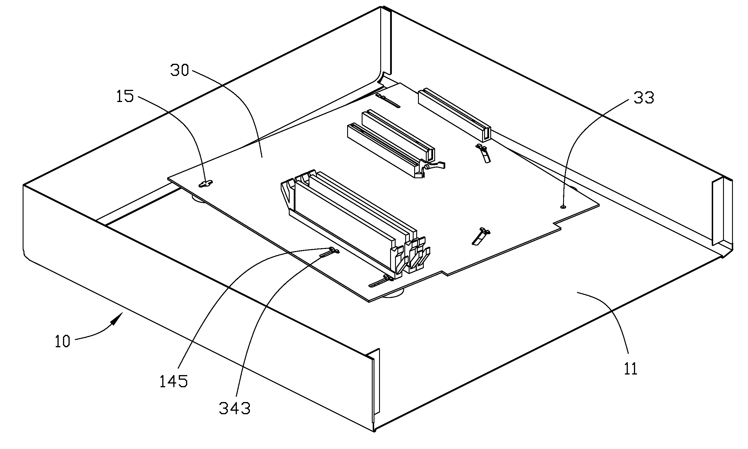
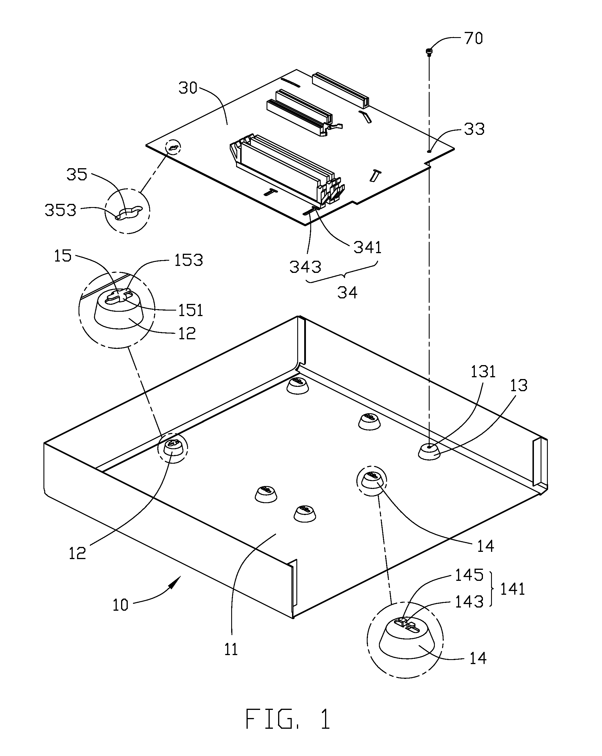
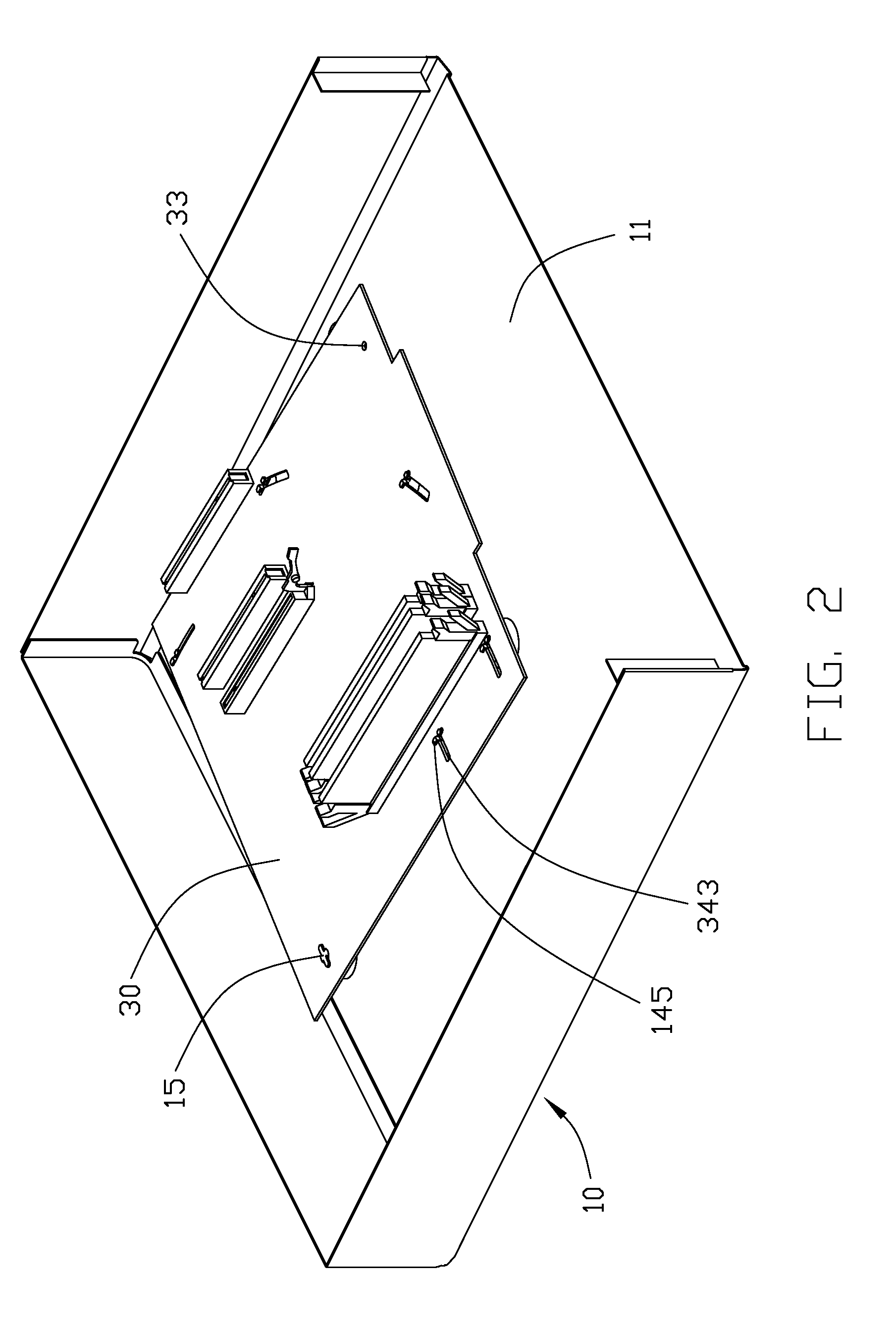
[0010]Referring to FIG. 1, a mounting apparatus is used to mount a motherboard 30 to a computer chassis 10.

[0011]The chassis 10 includes a bottom plate 11. The bottom plate 11 has a first convex projection 12, a second convex projection 13, and a plurality of third convex projections 14 protruded therefrom. These convex projections 12, 13, and 14 can be arranged in a rectangular shape. The first convex projection 12 and the second convex projection 13 are located at diagonal positions of the rectangular shape. A rotating shaft 15 is formed on the first convex projection 12. The rotating shaft 15 includes a pair of short legs 151 connected with the first convex projection 12, and a pair of long legs 153 located above the first convex projection 12. The pair of long legs 153 extends in a first direction, which is parallel to the bottom plate 11.

[0012]The second convex projection 13 defines a mounting hole 131. The third convex projection 14 forms a pair of clasps 141 thereon. Each cla...


PUM


Abstract

An apparatus includes a computer chassis and a motherboard. The motherboard defines a rotating hole, a clasp hole, and a through hole. The clasp hole has a clasp slot and an arcuate groove. The computer chassis includes a bottom plate, and a first, second, and third convex projections. A rotating shaft is formed on the first convex projection. A mounting hole is defined in the second convex projection. A clasp is formed on the third convex projection. The clasp includes a root connected with the third convex projection, and a bent portion. The motherboard is rotatable between a first and a second position. In the first position, the rotating shaft of the first convex projection is inserted in the rotating hole, and the bent portion of the clasp extends through the clasp slot. In the second position, the root of the clasp is located in the arcuate groove, and the though hole of the motherboard is aligned with the mounting hole of the second convex projection.

Description

BACKGROUND[0001]1. Technical Field[0002]The present embodiment relates to computer chassis, and particularly to a computer chassis that conveniently mounts a motherboard therein.[0003]2. Description of Related Art[0004]Conventionally, a motherboard is mounted to a computer chassis with fasteners, such as screws or bolts. However, when installing or removing the motherboard, a tool such as a screwdriver or a wrench is usually required, and tightening or removing the fasteners is laborious and time-consuming.[0005]Therefore, there is room for improvement within the art.BRIEF DESCRIPTION OF THE DRAWINGS[0006]Many aspects of the embodiments can be better understood with references to the following drawings. The components in the drawings are not necessarily drawn to scale, the emphasis instead being placed upon clearly illustrating the principles of the embodiments. Moreover, in the drawings, like reference numerals designate corresponding parts throughout the several views.[0007]FIG. 1...

Claims


Application Information

Patent Timeline
IPC IPC(8): H05K5/00
CPCG06F1/184
Inventor YEH, CHIN-WENLIN, ZHEN-NENG
Owner HONG FU JIN PRECISION IND (SHENZHEN) CO LTD
Why Eureka
Try Eureka