Method of Producing a Woven Artificial Turf

a technology of artificial turf and woven fibers, applied in the field of artificial turf, can solve the problems of difficult programing and manufacturing of tufted turf of different colors and designs

Inactive Publication Date: 2010-04-29
SHAW CONTRACT FLOORING SERVICES
View PDF53 Cites 9 Cited by
  • Summary
  • Abstract
  • Description
  • Claims
  • Application Information

AI Technical Summary

Problems solved by technology

Also, it is often difficult to program and manufacture tufted turf having different colors and designs as it requires manually changing the polyethylene, polypropylene or nylon pile being fed into the tufting machine and / or cutting design elements into the turf at installation.

Method used


Image

  • Method of Producing a Woven Artificial Turf
  • Method of Producing a Woven Artificial Turf
  • Method of Producing a Woven Artificial Turf

Examples


first embodiment

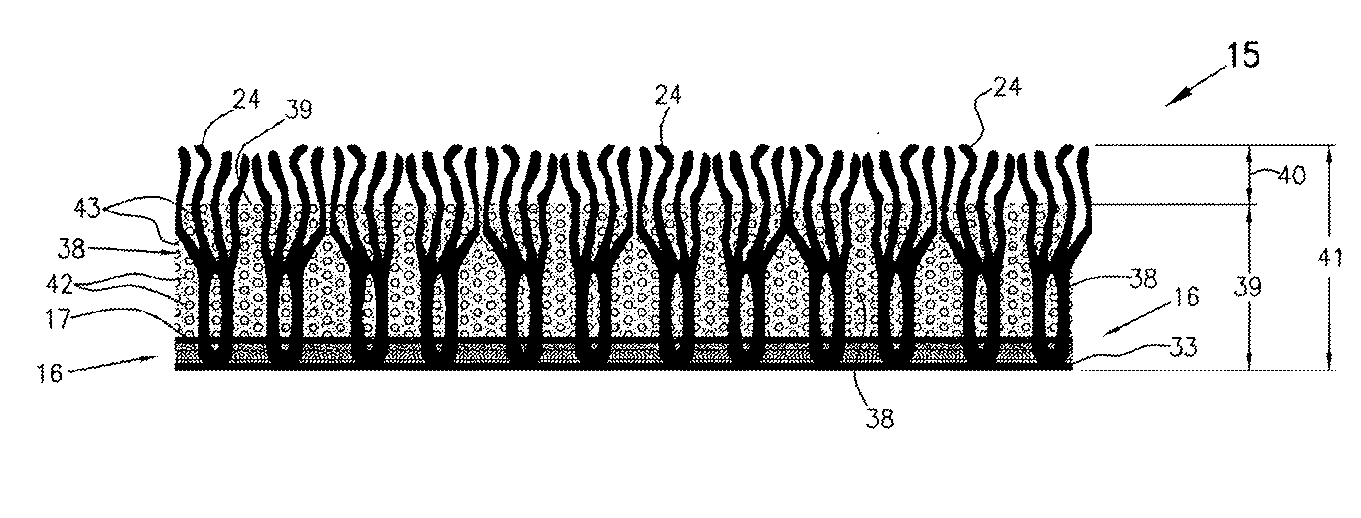
[0046]FIG. 2 shows the woven artificial turf system. As shown, in this embodiment the turf includes a primary backing layer 16 and a plurality of upstanding synthetic ribbons 24, representing blades of grass, extending upwardly from the upper surface 17 of backing layer 16. In this embodiment, ribbons 24 are fibrillated or slit-film extruded polyethylene ribbons. Fibrillation means that the yarn is of a flat, tape-like character and includes longitudinally extending slits across its width. With light brushing, these slits tend to split along the slits into several individual free standing strands of a width that is thinner then the full width of the yarn and thereby more closely resembles blades of grass. The Slit film-LSR yarn manufactured by Thiolon of Dayton, Tenn. may be used in the preferred embodiment.

[0047]As shown, an infill layer 38 is provided on the top surface 17 of backing layer 16. Infill layer 38 in this embodiment is a mixture of rubber 42 and sand 43 particles and i...

second embodiment

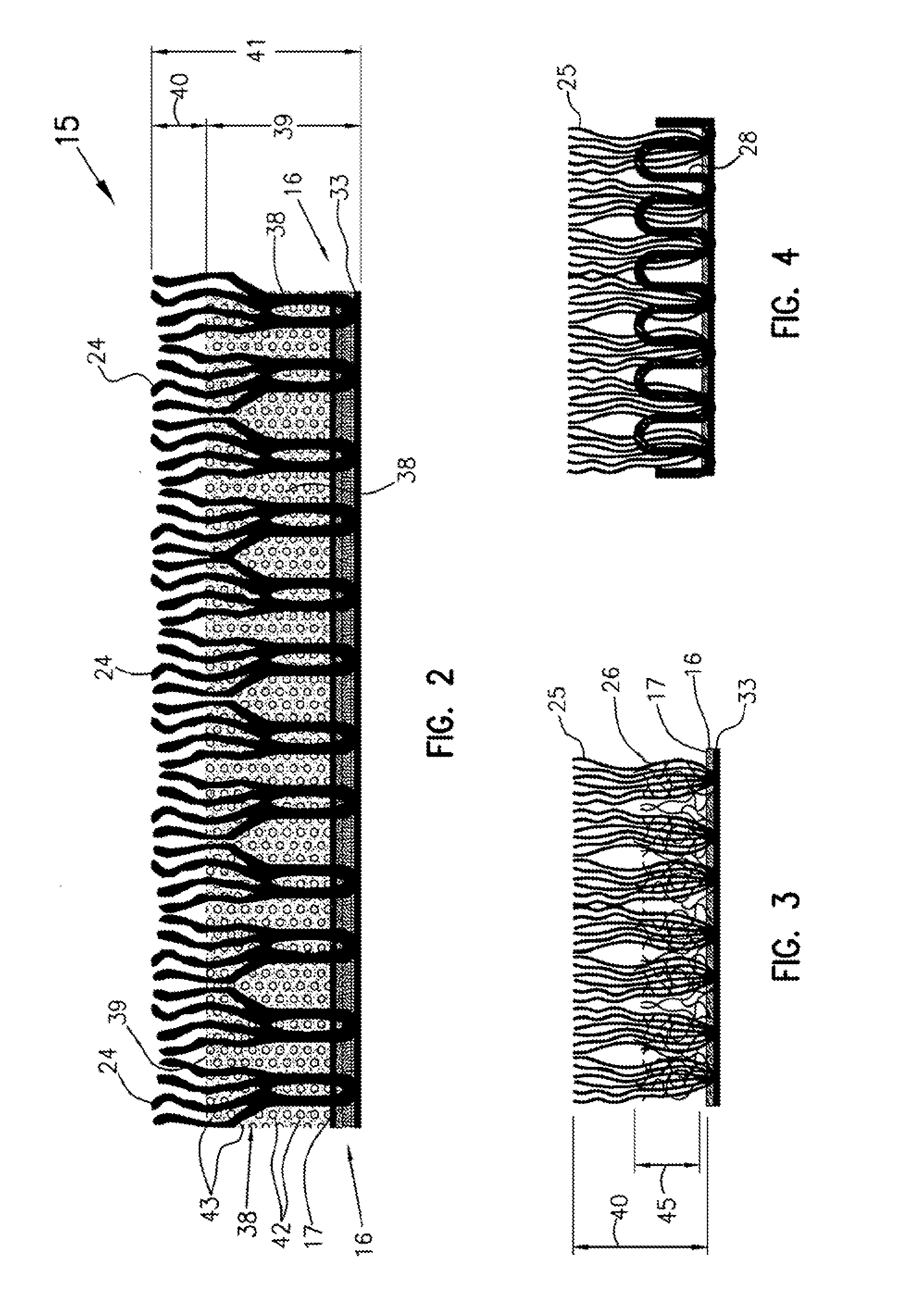
[0050]FIG. 3 shows a second embodiment in which the vertically extending ribbons comprise two different types of ribbon material. In this embodiment, the ribbons include a first type of ribbon 25, which is non-texturized, cut, long pile, multifilament ribbon, and a second type of ribbon 26, which is texturized, cut, short pile, multifilament ribbon.

[0051]Multifilament ribbon is not fibrillated. The PE-Monofilament ribbon manufactured by Thiolon of Daton, Tenn. may be used in the this embodiment.

[0052]Textured yarns are yarns that develop a desired stretch and bulk on subsequent processing. When woven or knitted into fabric, the cover, hand, and other aesthetics of the finished fabric better resemble the properties of the fabric constructed from spun yarn. Texturing is the process of crimping, imparting random loops, or otherwise modifying continuous filament yarn to increase cover, resilience, abrasion resistance, warmth, insulation, and moisture absorption or to provide a different...

fourth embodiment

[0058]FIG. 5 shows a This embodiment is similar to the embodiment shown in FIG. 3. However, in this embodiment, while long pile elements 25 are non-texturized, cut, long pile, multifilament ribbons, ribbons 29 are non-texturized, cut, short pile, fibrillated ribbons. Referring now to FIG. 11, ribbons 25 may be formed by weaving in as yarns 22 and 23 multifilament strands and weaving in as yarns 20 and 21 fibrillated strands. The pile height may be adjusted by either using a shrinking yarn type for pile elements 20 and 21 or by the mechanical adjustment of the weaving machine as discussed above with respect to the embodiment shown in FIG. 3. As with the embodiments shown in FIG. 3 and FIG. 4, this embodiment does not include an infill layer. However, it is contemplated that this embodiment may be used with an infill layer that extends some distance up the length of ribbons 25.


PUM

PropertyMeasurementUnit
lengthaaaaaaaaaa
lengthaaaaaaaaaa
heightaaaaaaaaaa

Abstract

Various embodiments are described relating to method of producing a synthetic field surface. In one embodiment, the method includes providing a plurality of warp yarns; providing a plurality of fill yarns; providing a plurality of pile yarns of a first type; providing a plurality of pile yarns of a second type; providing a plurality of dummy yards; weaving the plurality of pile yarns of the first type with the plurality warp yarns and the plurality of fill yarns for a first predetermined distance to form a backing; weaving the plurality of pile yarns of the first type with the plurality of dummy yarns to form a plurality of short hoops for a second predetermined distance; cutting the plurality of pile yarns of the first type to form a first plurality of upstanding ribbons representing grass to produce a synthetic field surface.

Description

CROSS REFERENCE TO RELATED APPLICATIONS[0001]This application claims the benefit of the filing date and is a continuation of U.S. patent application Ser. No. 11 / 401,144, filed on Apr. 10, 2006, entitled “WOVEN ARTIFICIAL TURF,” the disclosure of which is incorporated herein by reference for all purposes.TECHNICAL FIELD[0002]The present invention relates to artificial turf and, more particularly, to a woven artificial turf system.BACKGROUND INFORMATION[0003]Artificial turf sport fields are well-known in the prior art. They are generally used to replace natural grass surfaces and comprise rows of synthetic ribbons that extend vertically from a backing layer. The synthetic ribbons are designed to resemble grass and an infill layer of particulate material is often interspersed between the ribbons on the backing layer. In this arrangement, the synthetic ribbons are designed to extend a distance above the infill layer of particulate material. It is known in the prior art that the infill m...

Claims


Application Information

Patent Timeline
Patent Type & Authority Applications(United States)
IPC IPC(8): D03D41/00D03D15/04D03D27/12D03D15/567
CPCD03D27/00E01C13/08D10B2505/202D06N7/006D06N2201/12D06N7/0065D06N7/0068Y10T428/23936Y10T428/23957Y10T428/23914
Inventor KNAPP, TIMOTHY A.NICHOLLS, MARK H.SCHINKEL, JAMES A.
Owner SHAW CONTRACT FLOORING SERVICES
Why Eureka
Try Eureka