
Safety mechanism for a power path

a safety mechanism and power path technology, applied in the direction of contact mechanisms, electrical equipment, contact devices, etc., can solve the problems of insufficient safety of traditional electric equipments taken into account for their design, serious safety risks, and loss of original expected functions, so as to ensure the safety of using electric equipment

Inactive Publication Date: 2010-04-29
WANG LOAO
View PDF7 Cites 4 Cited by
  • Summary
  • Abstract
  • Description
  • Claims
  • Application Information

AI Technical Summary

Benefits of technology

[0009]It is a primary object of the invention to provide a safety mechanism using a mechanical structure to interrupt the power for a power path, so as to stop supplying power to the electric equipment and its control circuit and assure the safety of using the electric equipment.

Problems solved by technology

If the control circuit (or circuit board) fails, users cannot disconnect the power by pressing the stop key (or button), and thus a master power switch must be found immediately to disconnect the supply of all power, or else a serious consequence will result.
Obviously, the safety of traditional electric equipments taken into consideration for its design is insufficient.
In case the emergency breaking switch fails, the original expected function will be lost, and user s safety will be jeopardized seriously.
With the foregoing conventional design, the electric equipment is still in the standby mode of supplying power to the electric equipment and its control circuit, after the emergency breaking switch is pressed, and thus the power of the electric equipment has not been disconnected completely, and there is a risk for the electric equipment to continue its operation, and the aforementioned problem has not been overcome completely yet.
Although the probability for the occurrence of the breakdown is not too high, yet manufacturer cannot afford to take the chance or allow a fixed power to be supplied to electric equipments and their control circuit.
Obviously, supplying electric power in a fixed mode is a serious mistake.

Method used


Image

  • Safety mechanism for a power path
  • Safety mechanism for a power path
  • Safety mechanism for a power path

Examples


Embodiment Construction

[0022]The present invention will now be described in more detail hereinafter with reference to the accompanying drawings that show various embodiments of the invention.

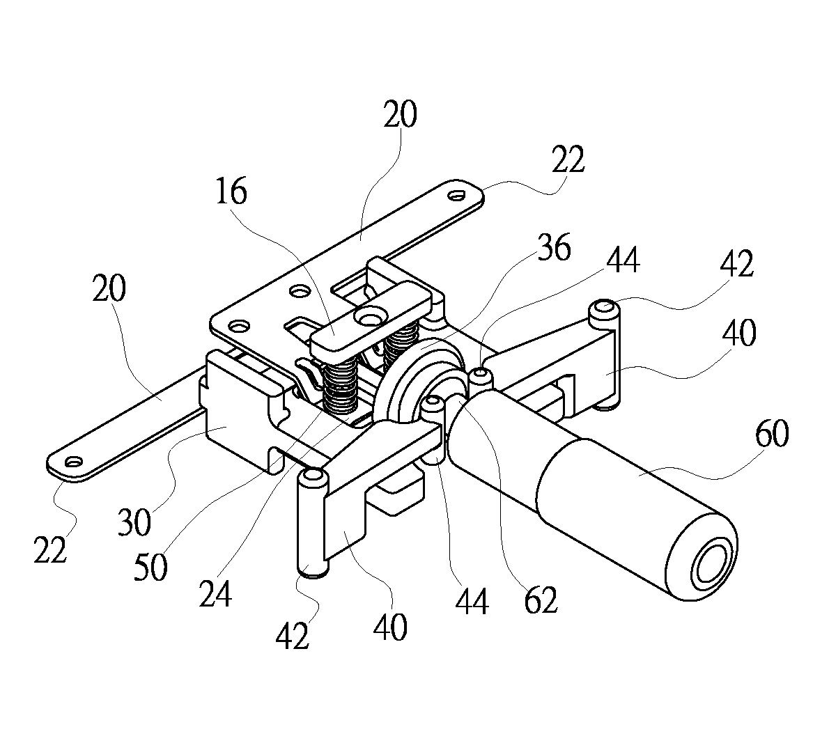
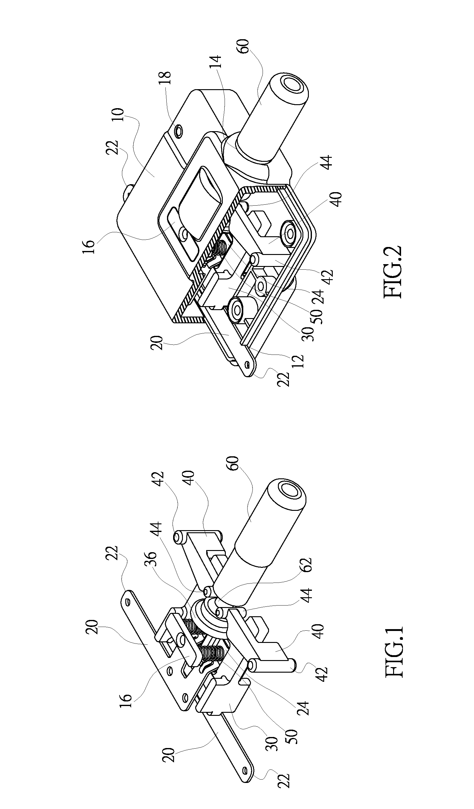
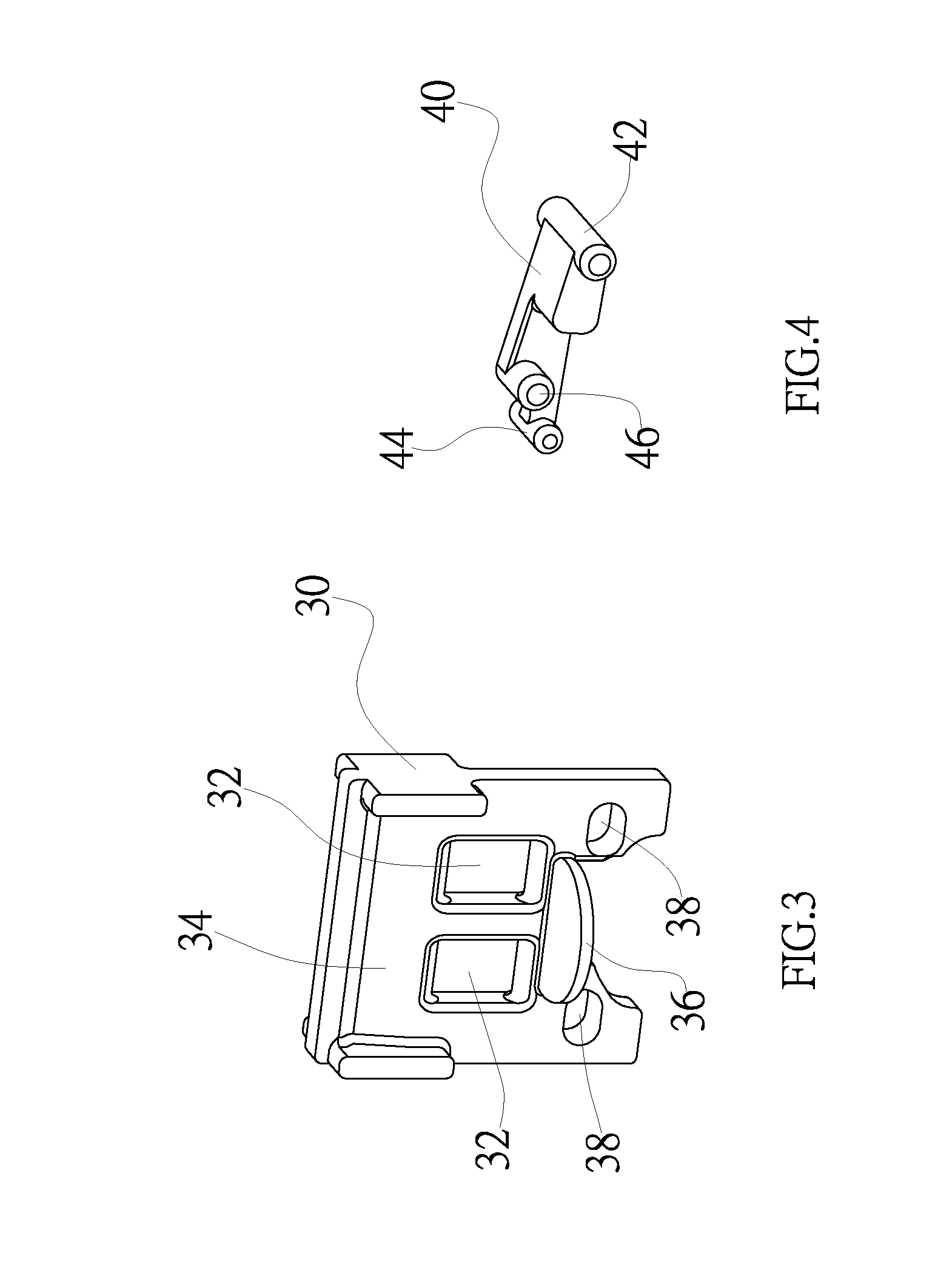
[0023]With reference to FIGS. 1 to 4, the invention comprises:

[0024]a casing 10, for accommodating components, and having an outlet hole 12 of a connecting end portion 22 of a conducting copper plate 20, a pin hole 14, a positioning board 16 of a resilient element 50 and a pivoting portion 18 of a rotating block 40;

[0025]two conducting copper plates 20, each having a connecting end portion 22 for connecting a power cable (not shown in the figure) or being used directly as a power connector, and a corresponding pin 24 disposed on another end of the conducting copper plate 20;

[0026]a slide base 30, disposed between the two conducting copper plates 20, and made of an insulating material, and having two hollow grooves 32 disposed proximate to the center of the slide base 30, and a side of the hollow groove 32 being an ins...


PUM


Abstract

A safety mechanism for a power path uses a mechanical structure for disconnecting a power path and providing a safety measure for electric equipments. The safety mechanism includes a casing, two conducting copper plates, a slide base, two rotating blocks, two sets of resilient elements and an insert pin. When the power path is connected, the insert pin must be always situated in a pin hole of the casing and inserted completely for contacting and conducting the corresponding pins of the two conducting copper plates. If it is necessary to disconnect a circuit in an emergency situation, users simply pull out the insert pin to rotate the rotating block accordingly, and allow the rotating block to synchronously drive the slide base to displace, such that the corresponding pins of the two conducting copper plates are forced to separate to form a disconnected circuit status.

Description

BACKGROUND OF THE INVENTION[0001]1. Fields of the Invention[0002]The present invention relates to a safety mechanism for a power path, and a safety mechanism that can be used directly as a power safety plug or installed between power paths of any one of the electric equipments, such that its mechanical breaker mechanism can be used to achieve the safety effect.[0003]2. Description of the Related Art[0004]In present electric equipments, a power cord or its connector is generally used for connecting a power source. In other words, if the connector is inserted into a power socket, an electric power is passed into a control circuit of an electric equipment and the electric equipment enters into a standby mode. Users simply press a start key (or button) of a control circuit (or a circuit board) to start the basic operation of the electric equipment, and it is an operating and controlling mode of a conventional basic application. In case a special or emergency situation occurs and it is n...

Claims


Application Information

Patent Timeline
Patent Type & Authority Applications(United States)
IPC IPC(8): H01H1/38
CPCH01H1/24H01H3/022H01H2001/0005H01H27/04H01H13/60
Inventor WANG, LOAO
Owner WANG LOAO
Learn More