Delivery systems for pressure protecting and delivering a submerged payload and methods for using the same

a technology for submerged payloads and delivery systems, applied in underwater equipment, special-purpose vessels, instruments, etc., can solve problems such as unsuitable for exporting information without being detected, expensive, impractical, and difficult to communicate the results of monitoring by submerged devices

Inactive Publication Date: 2010-05-06
IROBOT CORP
View PDF17 Cites 10 Cited by
  • Summary
  • Abstract
  • Description
  • Claims
  • Application Information

AI Technical Summary

Benefits of technology

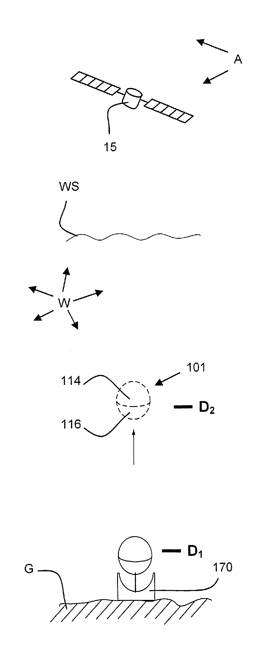
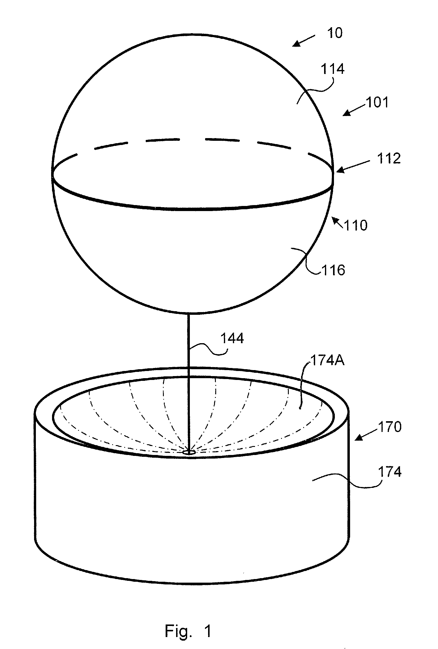
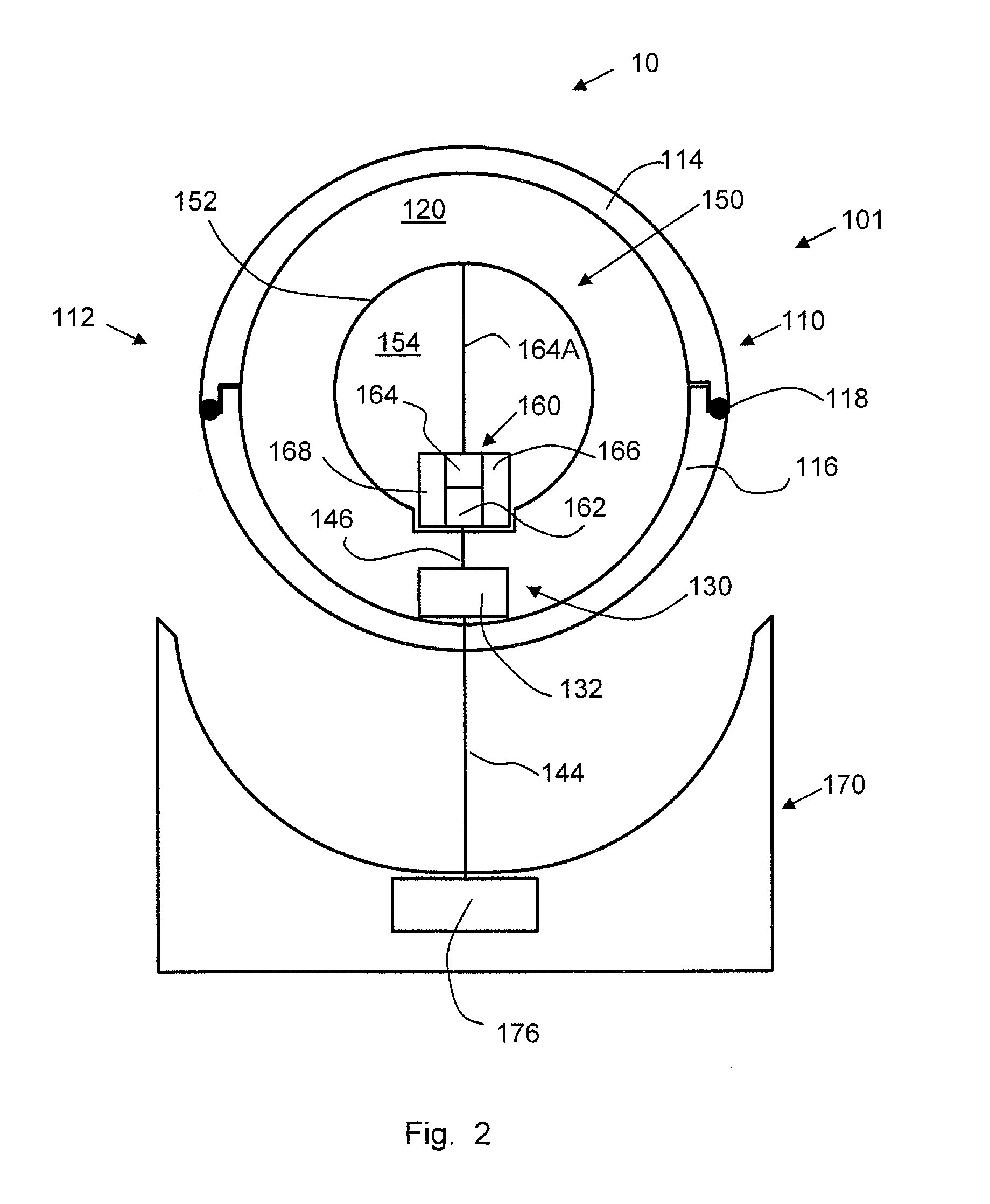
[0007]According to embodiments of the present invention, a payload delivery unit for protecting and delivering a payload submerged in a submersion medium comprises a container including a pressure resistant shell and a resilient seal device. The shell defines a containment chamber and includes first and second shell members having opposed first and second sealing faces, respectively. The seal device engages and is interposed between the first and second sealing faces. The container is configured and constructed such that: when the submersion medium applies an exterior pressure to the first and second shell members such that a shell pressure differential, defined as the exterior pressure less an interior pressure of the containment chamber, exceeds a prescribed pressure, the first and second shell members compressively load and deform the seal device to effect a seal between the first and second shell members that prevents ingress of the submersion medium into the containment chamber; and, when the shell pressure differential is less than the prescribed pressure, the seal device elastically rebounds to separate the first and second shell members to permit ingress of the submersion medium into the containment chamber.
[0008]According to method embodiments of the present invention, a method for protecting and delivering a payload submerged in a submersion medium includes providing a payload delivery unit comprising a container including a pressure resistant shell and a resilient shell device. The shell defines a containment chamber and includes first and second shell members having opposed first and second sealing faces, respectively. The seal device engages and is interposed between the first and second sealing faces. The method further includes: submerging the container with the payload mounted in the containment chamber; maintaining the payload delivery unit in a sealed condition wherein the submersion medium applies an exterior pressure to the first and second shell members such that a shell pressure differential, defined as the exterior pressure less an interior pressure in the containment chamber, exceeds a prescribed pressure, whereby the shell members compressively load and deform the seal device to effect a seal between the first and second shell members that prevents ingress of the submersion medium into the containment chamber; and thereafter causing the shell pressure differential to become less than the prescribed pressure, whereupon the seal device elastically rebounds to separate the first and second shell members to permit ingress of the submersion medium into the containment chamber.

Problems solved by technology

While such devices can be deployed without detection, communicating the results of monitoring by devices submerged in the sea is problematic.
A variety of systems have been described for raising an antenna above the sea, but they are either expensive, impractical, or readily detected, making them unsuitable for exporting information without being detected.

Method used


Image

  • Delivery systems for pressure protecting and delivering a submerged payload and methods for using the same
  • Delivery systems for pressure protecting and delivering a submerged payload and methods for using the same
  • Delivery systems for pressure protecting and delivering a submerged payload and methods for using the same

Examples


Embodiment Construction

[0027]The present invention now will be described more fully hereinafter with reference to the accompanying drawings, in which illustrative embodiments of the invention are shown. In the drawings, the relative sizes of regions or features may be exaggerated for clarity. This invention may, however, be embodied in many different forms and should not be construed as limited to the embodiments set forth herein; rather, these embodiments are provided so that this disclosure will be thorough and complete, and will fully convey the scope of the invention to those skilled in the art.

[0028]It will be understood that when an element is referred to as being “coupled” or “connected” to another element, it can be directly coupled or connected to the other element or intervening elements may also be present. In contrast, when an element is referred to as being “directly coupled” or “directly connected” to another element, there are no intervening elements present. Like numbers refer to like elem...


PUM


Abstract

A payload delivery unit for protecting and delivering a payload submerged in a submersion medium comprises a container including a pressure resistant shell and a resilient seal device. The shell defines a containment chamber and includes first and second shell members having opposed first and second sealing faces, respectively. The seal device engages and is interposed between the first and second sealing faces. The container is configured and constructed such that: when the submersion medium applies an exterior pressure to the first and second shell members such that a shell pressure differential, defined as the exterior pressure less an interior pressure of the containment chamber, exceeds a prescribed pressure, the first and second shell members compressively load and deform the seal device to effect a seal between the first and second shell members that prevents ingress of the submersion medium into the containment chamber; and when the shell pressure differential is less than the prescribed pressure, the seal device elastically rebounds to separate the first and second shell members to permit ingress of the submersion medium into the containment chamber.

Description

RELATED APPLICATION(S)[0001]This application claims the benefit of and priority from U.S. Provisional Patent Application No. 61 / 084,679, filed Jul. 30, 2008, and is a continuation-in-part (CIP) application claiming priority from U.S. patent application Ser. No. 12 / 332,734, filed Dec. 11, 2008, which claims the benefit of and priority from U.S. Provisional Patent Application Ser. No. 61 / 013,184, filed Dec. 12, 2007, the disclosures of which are incorporated herein by reference.STATEMENT OF GOVERNMENT SUPPORT[0002]This invention was made with support under Small Business Innovation Research (SBIR) Program No. N00014-07-C-0197 awarded by the United States Navy Office of Naval Research. The Government has certain rights in the invention.FIELD OF THE INVENTION[0003]The present invention relates to submersible devices and, more particularly, to systems for protecting and delivering submersible payloads.BACKGROUND OF THE INVENTION[0004]Monitoring littoral seas without being detected can be...

Claims


Application Information

Patent Timeline
Patent Type & Authority Applications(United States)
IPC IPC(8): B63G8/00H04B11/00
CPCB63B22/003B63B22/06B63B22/12B63B22/24B63B2022/006B63G6/00B63G9/00H04B11/00H04B13/02
Inventor ISRAEL, STEVEN CRAIGGERMANA, DOMINIC CAZAGREINER, CRAIG A.VOSBURGH, FREDERICK
Owner IROBOT CORP
Why Eureka
Try Eureka