Downhole Tool

a tool and tool body technology, applied in the field of downhole tools, can solve problems such as difficulty or inability to withdraw, and achieve the effect of minimising wear and minimising wear of bars

Inactive Publication Date: 2010-05-06
REAMERCO
View PDF13 Cites 40 Cited by
  • Summary
  • Abstract
  • Description
  • Claims
  • Application Information

AI Technical Summary

Benefits of technology

[0033]Where the tool is an under-reamer, said bars are provided with cutting elements to effect under-reaming when the tool is actuated in a well bore having a pilot hole receiving the tool.
[0034]Said body is thickened in the region of said slots and bars to support said bars. The body may have fins ahead of said slots having dimensions to match said pilot hole and bear against its surface and stabilise the tool, in use, said fins being provided with a hardened wear surface to minimise wear.
[0035]Alternatively, the tool may be an adjustable stabiliser, said bars being provided with hardened wear surfaces to minimise wear of the bars, in use.

Problems solved by technology

On the other hand, when components get worn or contorted by their interaction with the bore hole, they may be difficult or impossible to withdraw.
This might be very problematic with an under-reamer where, to get the tool out through a narrow casing above the reamer, the reamer must be withdrawn (deactuated).

Method used


Image

  • Downhole Tool
  • Downhole Tool
  • Downhole Tool

Examples


Embodiment Construction

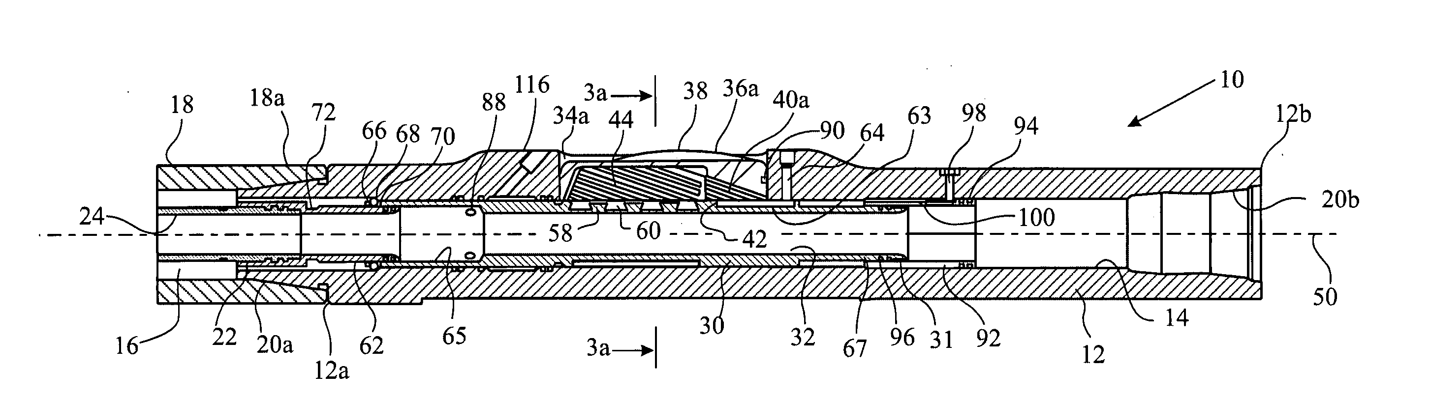
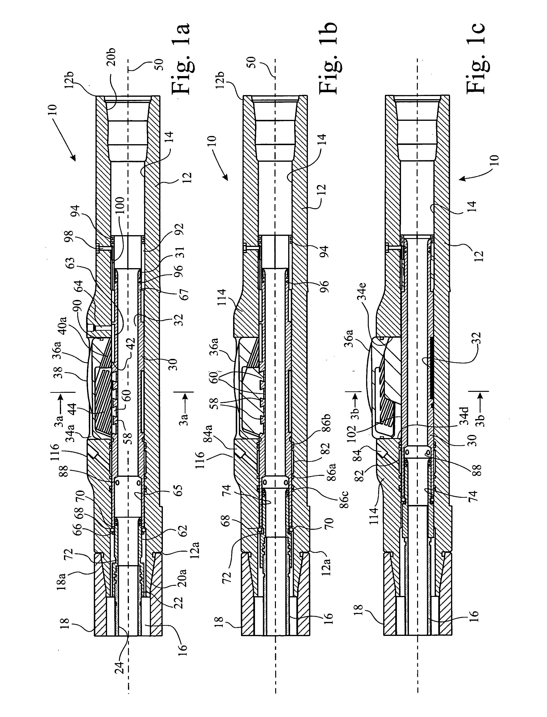
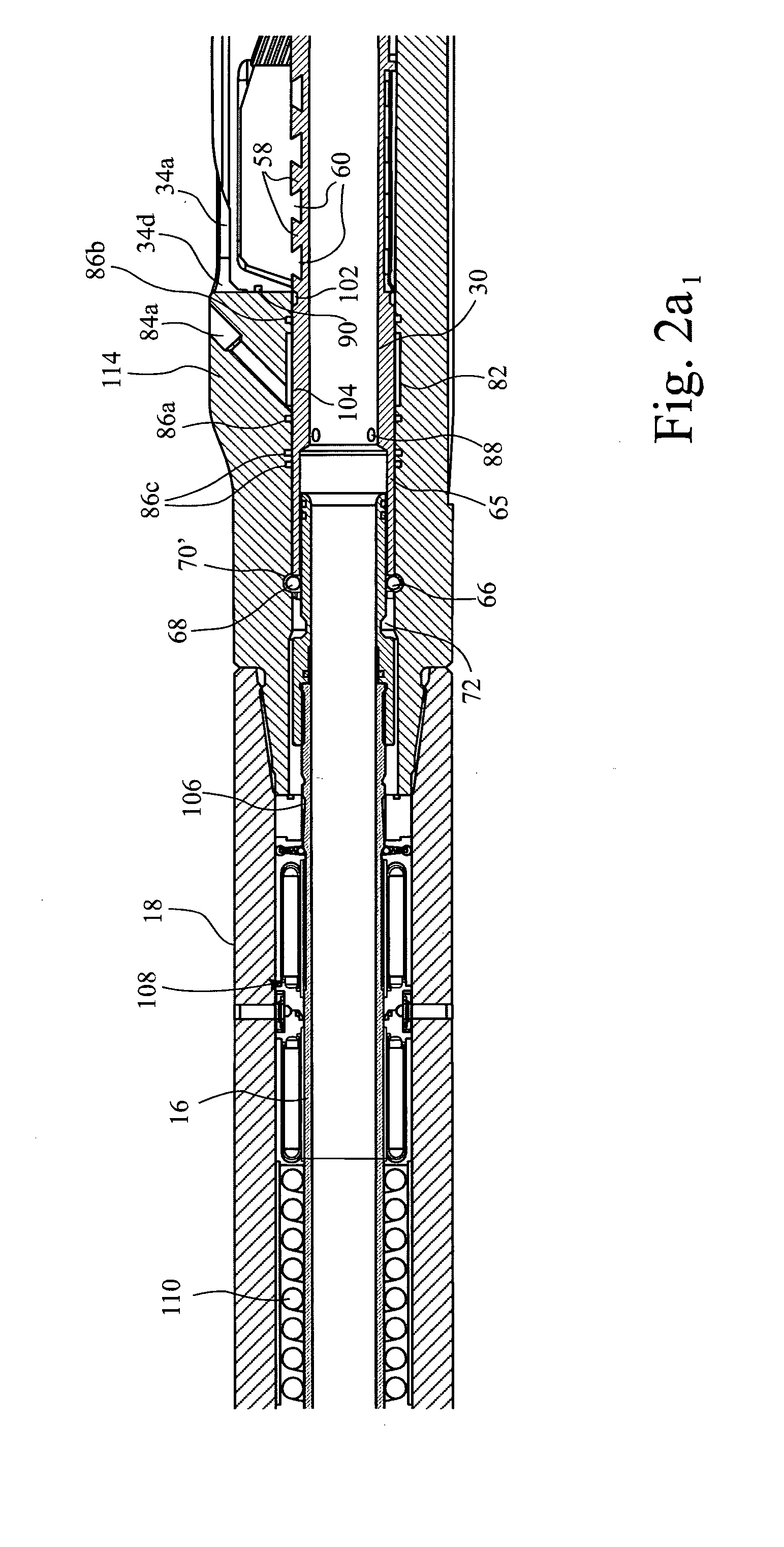
[0044]In FIGS. 1 to 3 of the drawings, an under-reamer 10 comprises a body 12 having a through-bore 14 along a longitudinal axis 50 of the tool 10. A mandrel 16 actuates the tool 10 and is a component of an actuation mechanism 18, only one end of which is shown in the drawings. The actuation mechanism 18 is connected at its end 18a to end 12a of the body 12 by a standard screw thread connection 20a. The other end 12b of the tool 10 comprises a female connection 20b.

[0045]The actuation mechanism 18 forms no part of the invention and may be in the form disclosed in WO-A-00 / 53886, U.S. Pat. No. 5,483,987, U.S. Pat. No. 6,289,999 (the entire disclosures of which are incorporated herein by reference), or any suitable means. Connected to the end of the mandrel 16 is mandrel end 22, which, conveniently, is screw threaded to the mandrel 16. However, in suitable circumstances end 22 may be integral with the mandrel 16 and henceforth is considered a part of the mandrel 16. In the drawings, m...


PUM


Abstract

A downhole tool (10′) comprises a body (12′) having a longitudinal axis and a body through-bore (14′), a slot (34′) communicating the outside of the body with the body through-bore. A sleeve actuator (30′) mandrel also has a bore and is selectively axially slidable in the body through-bore. A hollow bar (36′) is slidable with a radial component in the slot. At least two levers (210), each pivoted to the mandrel (about a first axis perpendicular the longitudinal axis) extend into the hollow bar and are pivoted thereto (about a second axis parallel the first axis). The levers lie in an actuation plane perpendicular the first and second axes and containing the slot. The levers are disposed at an inclined angle with respect to the longitudinal axis so that longitudinal motion of the mandrel translates into radial movement of the bar.

Description

CROSS-REFERENCE TO RELATED APPLICATIONS[0001]This application claims the benefit of, and priority to, application number 0704484.5, which was filed in the United Kingdom on Mar. 8, 2007, which application is incorporated herein by reference as if reproduced in full below.STATEMENT REGARDING FEDERALLY SPONSORED RESEARCH OR DEVELOPMENT[0002]Not applicable.FIELD OF THE INVENTION [0003]The present invention relates to a downhole tool, in particular an under-reamer.BACKGROUND[0004]Our pending international application publication number WO2006 / 072761 (the entire disclosure of which is incorporated herein by reference) discloses a downhole tool comprising:[0005]a body having a longitudinal axis and a body through-bore, a slot communicating the outside of the body with the body through-bore;[0006]a sleeve actuator mandrel having a sleeve actuator mandrel through-bore and being selectively axially slidable in the body through-bore;[0007]a flange on the sleeve actuator mandrel extending into...

Claims


Application Information

Patent Timeline
Patent Type & Authority Applications(United States)
IPC IPC(8): E21B10/32E21B17/10E21B17/12
CPCE21B17/1014E21B10/32E21B17/10E21B33/128
Inventor OLLERENSHAW, ANDREWRUSSELL, MARK
Owner REAMERCO
Why Eureka
Try Eureka