
Method of setting mold clamping force of injection molding machine

a technology of injection molding machine and clamping force, which is applied in the direction of auxillary shaping apparatus, manufacturing tools, ceramic shaping apparatus, etc., can solve the problems of unnecessarily increasing consumption energy and earlier deformation of molds, and achieves cost reduction, effective differentiation, and simplified configuration.

Active Publication Date: 2010-05-06
NISSEI PLASTIC IND CO LTD
View PDF7 Cites 11 Cited by
  • Summary
  • Abstract
  • Description
  • Claims
  • Application Information

AI Technical Summary

Benefits of technology

[0008]With the method of setting a mold clamping force of the injection molding machine M according to the present invention, the following significant benefits are obtained.
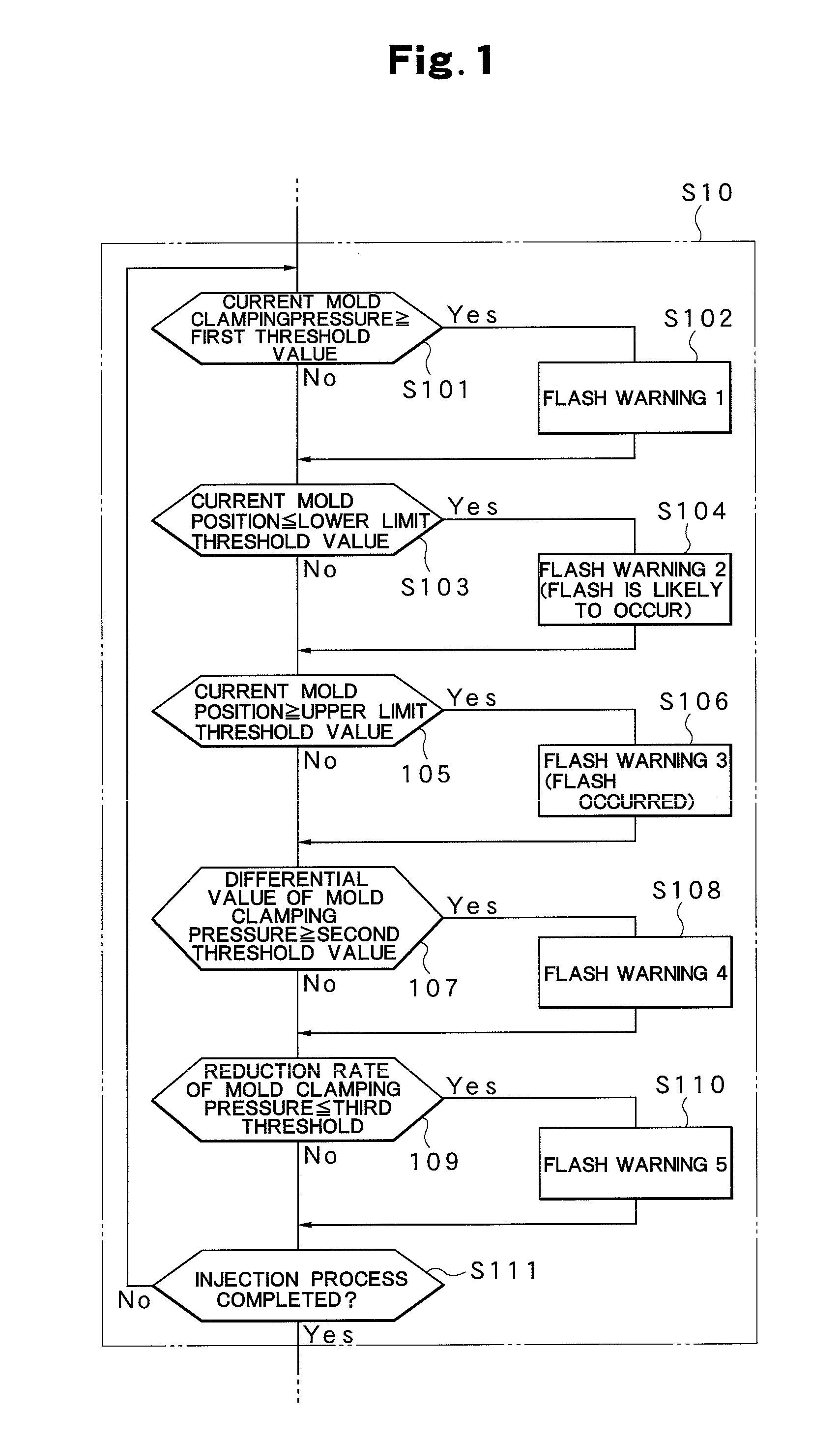
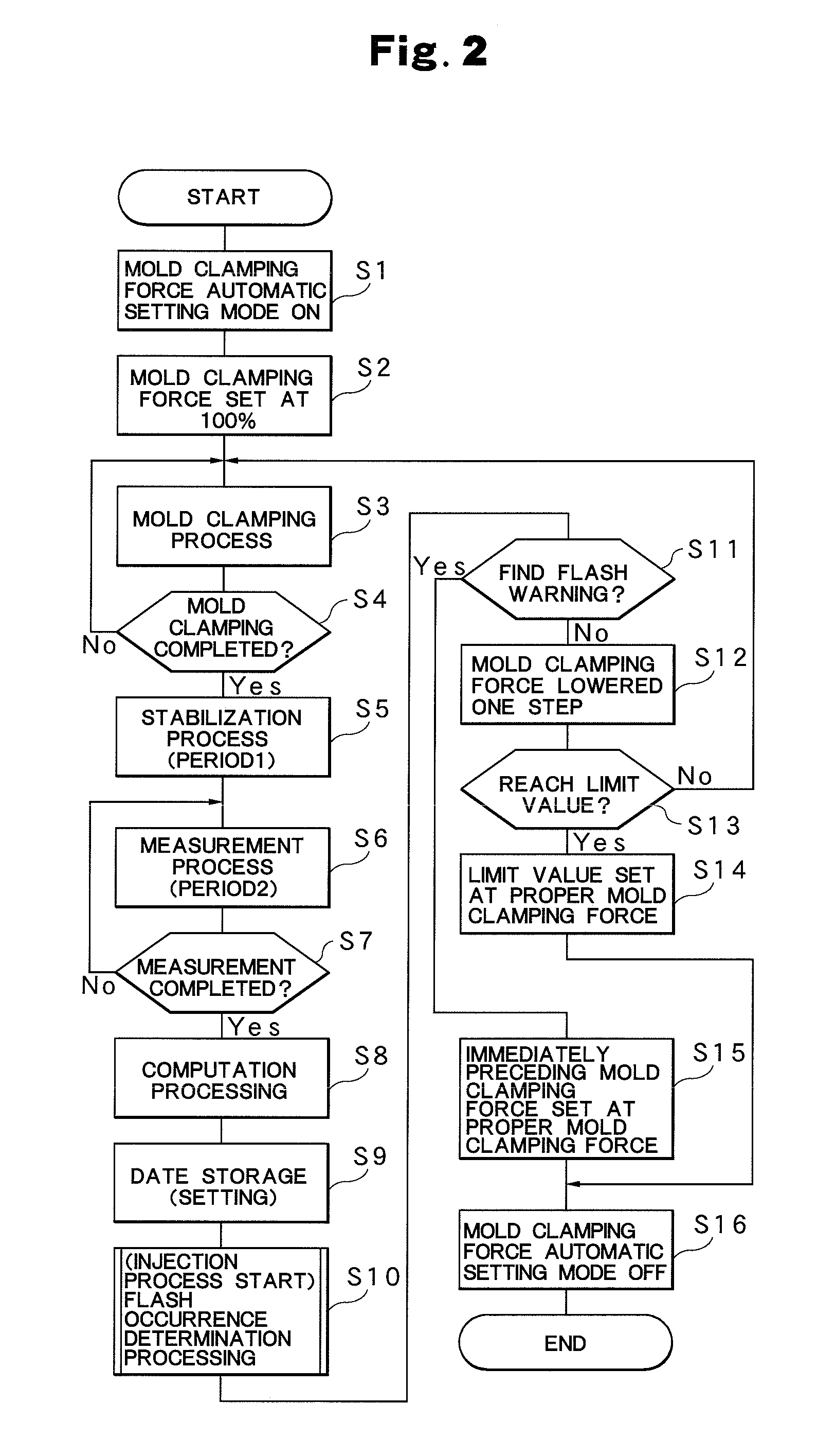
[0009](1) The mold clamping pressure Pc in the injection process is detected, and a plurality of different monitored elements (Pc, Pcd and Pcr) corresponding to the variation of the mold clamping pressure Pc are monitored, and thus, if at least one of the monitored elements is varied to exceed the predetermined threshold value, a mold clamping force obtained by increasing the mold clamping force at the time of the production of such a variation by a predetermined amount is set as the proper mold clamping force Fs, with the result that it is possible not only to accurately and reliably set the required minimum proper mold clamping force Fs with which no flash is produced but also to easily set the more accurate proper mold clamping force Fs in an automatic manner.
[0010](2) According to one preferred aspect, as the mold clamping device Mc, a hydraulic direct-pressure type mold clamping device that clamps the mold 2 with the mold clamping cylinder 8 is applied, and thus the reduction rate Pcr of the mold clamping pressure Pc with respect to time based on the fact that oil leaks from the mold clamping cylinder 8 in the injection process can be used as a monitor element.
[0011](3) According to another preferred aspect, the mold clamping pressure Pc, the differential value Pcd of the mold clamping pressure Pc with respect to time and the reduction rate Pcr of the mold clamping pressure Pc with respect to time are included in a plurality of monitored elements, and thus it is possible to utilize substantially one detected element as three (a plurality of) different monitored elements, with the result that it is possible to facilitate the simplification of configuration and cost reduction.
[0012](4) According to another preferred aspect, as the differential value Pcd, a differential value obtained by directly differentiating the mold clamping pressure Pc or a differential value obtained by the least-squares method can be utilized, and thus, it is possible to select a more effective differentiation method according to the behavior of the detected mold clamping pressure Pc.
[0013](5) According to another preferred aspect, as a mold clamping force obtained by increasing the mold clamping force by a predetermined amount, the immediately set mold clamping force is used, and thus it is possible to easily and accurately set the proper mold clamping force Fs by utilizing the immediately preceding mold clamping force with which flash has been already found to be prevented from occurring.

Problems solved by technology

In this type of mold clamping device, for example, a high-pressure mold clamping is performed at the maximum mold clamping force of the mold clamping device to achieve secure clamping without the occurrence of flash or the like; however, since an excessive mold clamping force is applied to the mold, the mold is degraded earlier and consumption energy is unnecessarily increased, and stains and damages on the surface of cavities, such as weld marks, burns and black streaks, are produced due to insufficient gas removal, with the result that it is necessary to perform repair process.

Method used


Image

  • Method of setting mold clamping force of injection molding machine
  • Method of setting mold clamping force of injection molding machine
  • Method of setting mold clamping force of injection molding machine

Examples


Embodiment Construction

[0028]The present invention will now be described in detail, using a preferred embodiment of the present invention, based on the accompanying drawings. The accompanying drawings are not used for specifying the present invention but are used to make the invention easily understood. The detailed description of known parts will be omitted so as not to make the invention unclear.

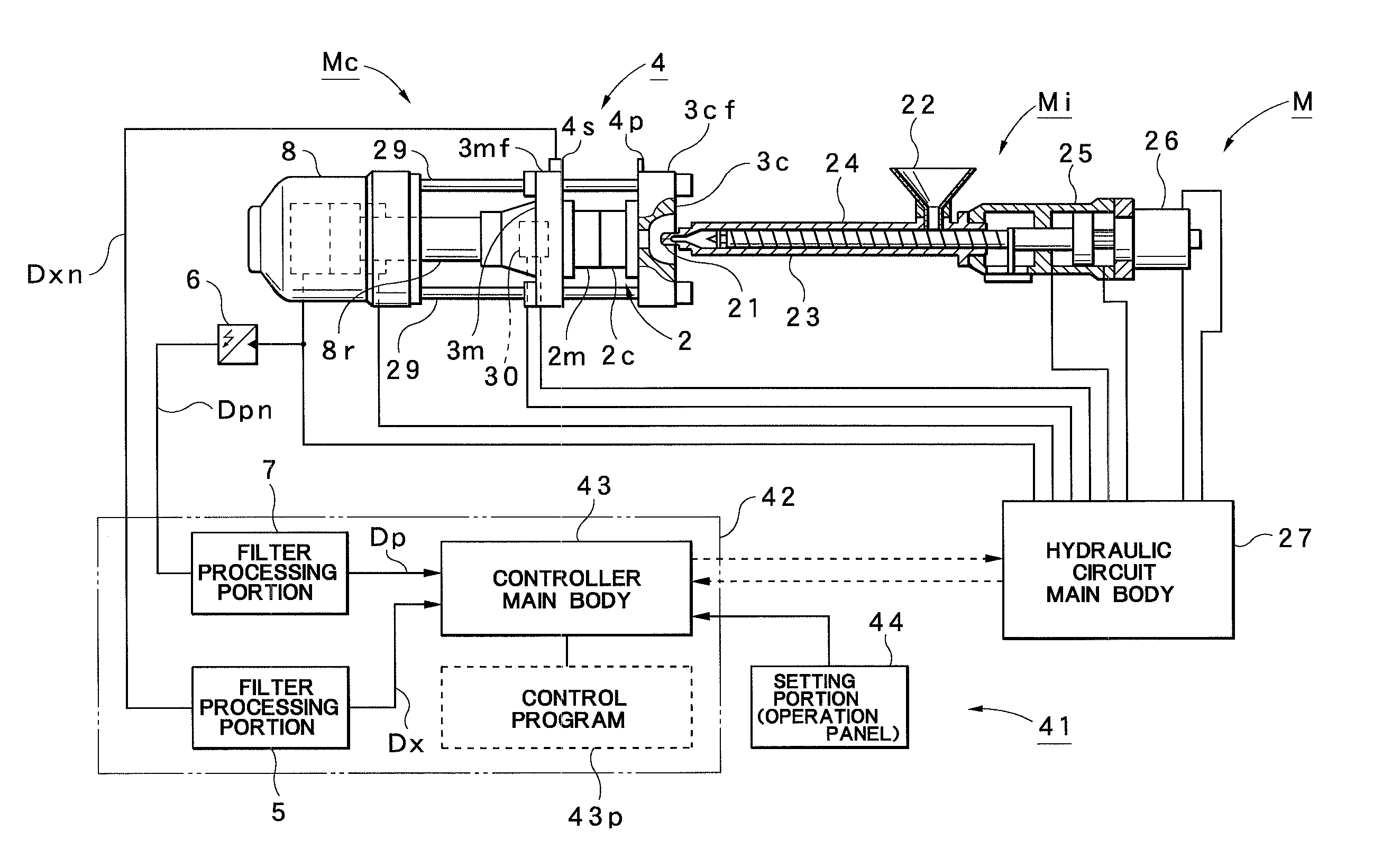
[0029]The configuration of an injection molding machine M that can perform a method of setting a mold clamping force according to this embodiment will first be described with reference to FIGS. 3 and 4.

[0030]In FIG. 3, the reference numeral M represents an injection molding machine, and it is provided with an injection device Mi and a mold clamping device Mc. The injection device Mi is provided with a heating cylinder 23 that has an injection nozzle 21 at the front end and a hopper 22 for material supply at the rear portion; the heating cylinder 23 incorporates a screw 24. At the rear portion of the heating cyli...


PUM

PropertyMeasurementUnit
timeaaaaaaaaaa
mold clamping forceaaaaaaaaaa
mold clamping pressureaaaaaaaaaa

Abstract

When test molding is performed by sequentially clamping a mold with a mold clamping force (100%, 80%, 70%, ...) obtained by sequentially lowering a mold clamping force by a predetermined amount from the maximum mold clamping force (100%), a mold clamping pressure Pc in an injection process is detected and a plurality of different monitored elements (Pc, Pcd and Per) corresponding to the variation of the mold clamping pressure Pc are monitored, and thus it is detected that at least one of the monitored elements is varied to exceed a predetermined threshold, a mold clamping force obtained by increasing a mold clamping force at the time of the production of the variation by a predetermined amount is set as a proper mold clamping force Fs.

Description

TECHNICAL FIELD[0001]The present invention relates to a method of setting a mold clamping force of an injection molding machine, and such a method is suitably used to set a mold clamping force smaller than the maximum mold clamping force when a mold is clamped by a mold clamping device.BACKGROUND ART[0002]An injection molding machine is generally provided with a mold clamping device for clamping a mold. In this type of mold clamping device, for example, a high-pressure mold clamping is performed at the maximum mold clamping force of the mold clamping device to achieve secure clamping without the occurrence of flash or the like; however, since an excessive mold clamping force is applied to the mold, the mold is degraded earlier and consumption energy is unnecessarily increased, and stains and damages on the surface of cavities, such as weld marks, burns and black streaks, are produced due to insufficient gas removal, with the result that it is necessary to perform repair process. Thu...

Claims


Application Information

Patent Timeline
Patent Type & Authority Applications(United States)
IPC IPC(8): B29C45/76
CPCB29C45/67B29C45/7653B29C2945/76006B29C2945/7601B29C2945/7623B29C2945/76387B29C2945/76498B29C2945/76702
Inventor KUDO, YOSHIAKIHAKODA, TAKASHINAKAMURA, KIYOSHIMOROZUMI, SUSUMU
Owner NISSEI PLASTIC IND CO LTD
Learn More