Camera device

a camera and lens technology, applied in the field of camera devices, can solve the problems of inability to read the image information correctly, the amount of the image information is not clear, and the surveillance camera cannot capture the image pattern of the image information clearly, so as to achieve the effect of easy setting information thereto

Inactive Publication Date: 2010-05-06
MITSUBISHI ELECTRIC CORP
View PDF4 Cites 58 Cited by
  • Summary
  • Abstract
  • Description
  • Claims
  • Application Information

AI Technical Summary

Benefits of technology

[0020]In accordance with the present invention, the setting information is converted into the plurality of image patterns, the plurality of image patterns are displayed in time sequence according to the predetermined sequence, and the setting information is reproduced from the image information which the camera device acquires by capturing this displayed description to set the setting information to the camera device. Therefore, even if each of the plurality of image patterns is not a complicated one, the amount of information of the setting information ...

Problems solved by technology

A problem with conventional technologies is, however, that because in order to ensure the amount of information included in image information about an image patter the image pattern is made to become complicated, it is impossible to read correctly the image information whose amount of information is large by using a camera unless the camera supports close-up image capturing or unless the display position of the image information to the camera is accurately adjusted.
For example, because a surveillance camera is based on the premise that it captures an area which is the target for surveillance over a wide region of the area, and a lens having a focal length according to this capturing is therefore disposed, close-up image capturing of image information as mentioned above results in a shift of the focus, and therefore the surveillance camera cannot capture the image pattern of the image information clearly and cannot analyze the image information to acquire setting information.
In contrast, when the image information is placed too far away from the image pickup unit of the camera, the image pickup unit of the camera cannot pick up the complicated image pattern because of its insufficient resolution.
If the image pattern is a simplified one,...

Method used


Image

  • Camera device
  • Camera device
  • Camera device

Examples


embodiment 1

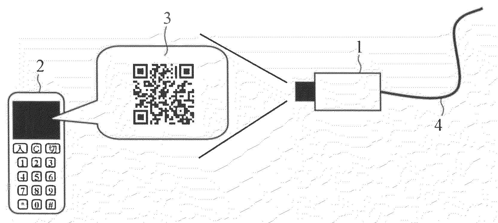
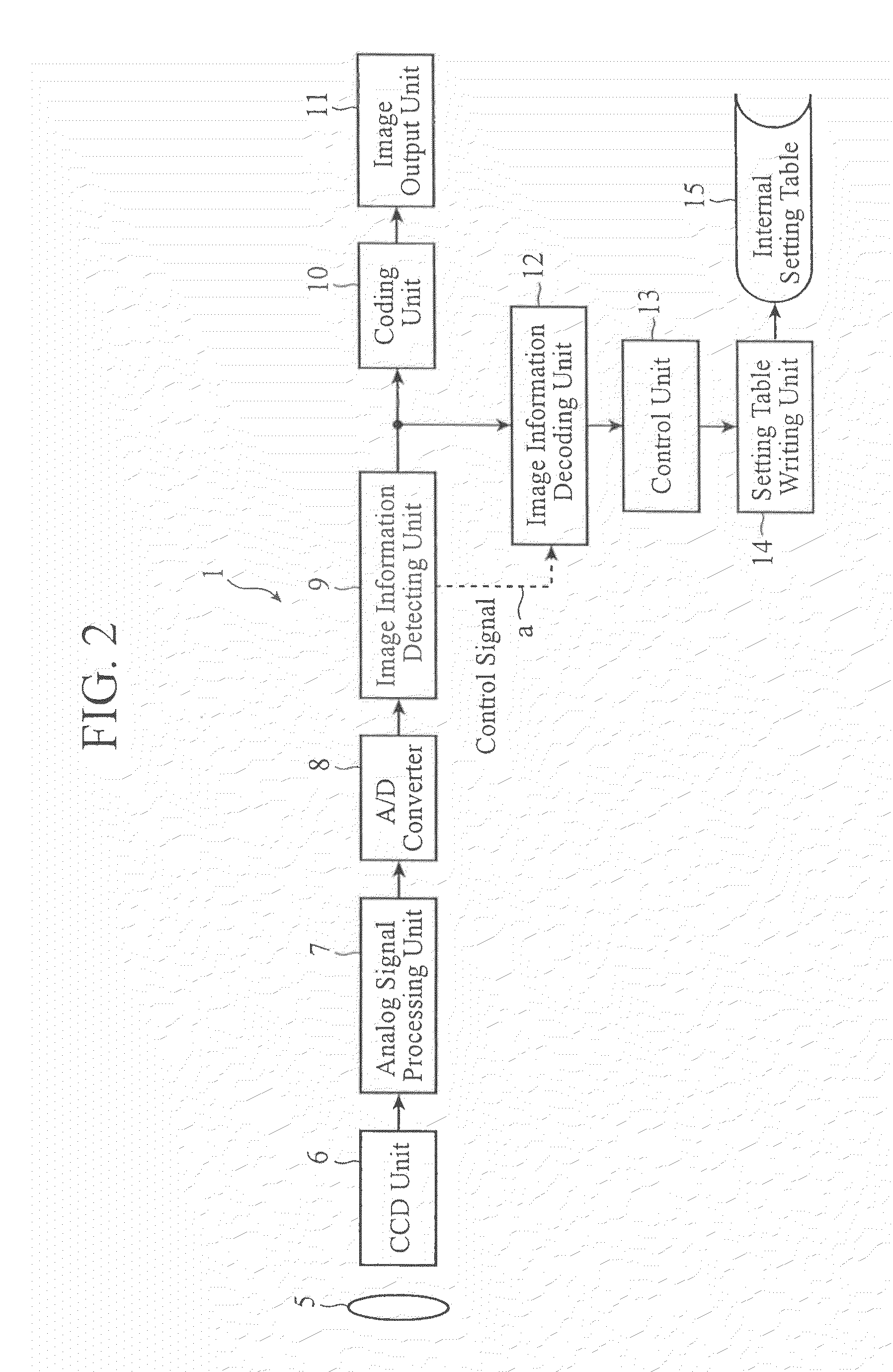
[0031]FIG. 1 is a view showing schematically a camera system which uses a camera device in accordance with Embodiment 1 of the present invention, and shows a case in which the camera device in accordance with this embodiment is applied to a surveillance camera system. In FIG. 1, the surveillance camera (the camera device) 1 is an IP (Internet Protocol) camera that can communicate with equipment on a not-shown IP network via a LAN (Local Area Network) cable 4, and performs digital compression coding on a captured image and then outputs the coded image to the equipment on the IP network. In a case in which such an IP camera is installed, it is necessary to set information about image capturing conditions, such as image quality, and the operating conditions of network communications to the camera.

[0032]In Embodiment 1, as shown in FIG. 1, the information to be set to the surveillance camera 1 is set to the camera by using image information 3 which is an image pattern (a two-dimensional...

embodiment 2

[0073]A camera device in accordance with the present Embodiment 1 additionally includes a function of outputting information indicating whether or not an information setting has been made thereon as desired to outside the camera device in addition to the structure of the surveillance camera shown in above-mentioned Embodiment 1.

[0074]FIG. 6 is a block diagram showing the structure of the camera device in accordance with Embodiment 2 of the present invention. In FIG. 6, the surveillance camera 1A in accordance with Embodiment 2 includes a setting result output unit 23 that outputs the setting results to outside the surveillance camera, in addition to the structure explained in above-mentioned Embodiment 1 with reference to FIG. 2. The setting result output unit 23 generates the body of an email having a description specified by a control unit 13, and also transmits the email to a preset mail server on an IP network according to a mail transfer protocol, such as SMTP (Simple Mail Tran...

embodiment 3

[0084]A surveillance camera in accordance with this Embodiment 3 has an operation mode for information setting, and performs a detecting process of detecting image patterns including setting information only in this operation mode for information setting.

[0085]FIG. 8 is a block diagram showing the structure of the camera device in accordance with Embodiment 3 of the present invention. In FIG. 8, the surveillance camera 1B in accordance with Embodiment 3 includes an operation-mode-based output switching unit 26, in addition to the structure explained in above-mentioned Embodiment 1 with reference to FIG. 2. The operation-mode-based output switching unit 26 switches the output destination of a digital image signal inputted thereto from an A / D converter 8 between a path to a coding unit 10 and a path to an image information detecting unit 9 on the basis of switch information for switching between operation modes. In FIG. 8, the same components as those shown in FIG. 2 or like component...


PUM


Abstract

Setting information is converted into a plurality of image patterns (22), and the plurality of image patterns (22) are displayed in time sequence according to a predetermined sequence. A camera device reproduces the setting information from image information (3) which the camera device acquires by capturing the displayed description to set the setting information thereto.

Description

BACKGROUND OF THE INVENTION[0001]1. Field of the Invention[0002]The present invention relates to a camera device for use in a camera system, such as a surveillance-oriented CCTV (Closed Circuit TeleVision) system. More particularly, it relates to a camera device which implements a simplified operation of providing setting information.[0003]2. Description of Related Art[0004]Conventionally, in order to simplify an operation of setting image capturing conditions, operating conditions, and so on to a digital camera, there is disclosed a technology of providing recorded image information about an image of a bar code or a two-dimensional image code into which setting information is converted, capturing this image information using the digital camera, and analyzing the image information to set the description recorded in the image information to the digital camera (for example, refer to patent references 1 and 2).[0005]Patent reference 3 describes a camera-equipped mobile phone that sets ...

Claims


Application Information

Patent Timeline
IPC IPC(8): H04N5/335H04N5/225H04N5/232H04N7/18
CPCH04N5/232H04N5/23206H04N23/661H04N23/60
Inventor KUWAHARA, NAOKISAKATA, KOJIHAGA, TETSUJITAKEUCHI, KOICHI
Owner MITSUBISHI ELECTRIC CORP
Why Eureka
Try Eureka