
MEMS anchors

a technology of anchors and ms, applied in the field of display, can solve problems such as deflection, and achieve the effect of avoiding obscuring the purpos

Active Publication Date: 2010-05-06
SNAPTRACK
View PDF99 Cites 64 Cited by
  • Summary
  • Abstract
  • Description
  • Claims
  • Application Information

AI Technical Summary

Benefits of technology

[0007]This section is for the purpose of summarizing some aspects of the present invention and to briefly introduce some preferred embodiments. Simplifications or

Problems solved by technology

Such a deflection can occur due to mechanical shock applied to the shutter or due to attraction between the shutter and the substrate.

Method used


Image

  • MEMS anchors
  • MEMS anchors
  • MEMS anchors

Examples


Embodiment Construction

[0032]To provide an overall understanding of the invention, certain illustrative embodiments will now be described, including apparatus and methods for displaying images. However, it will be understood by one of ordinary skill in the art that the systems and methods described herein may be adapted and modified as is appropriate for the application being addressed and that the systems and methods described herein may be employed in other suitable applications, and that such other additions and modifications will not depart from the scope hereof.

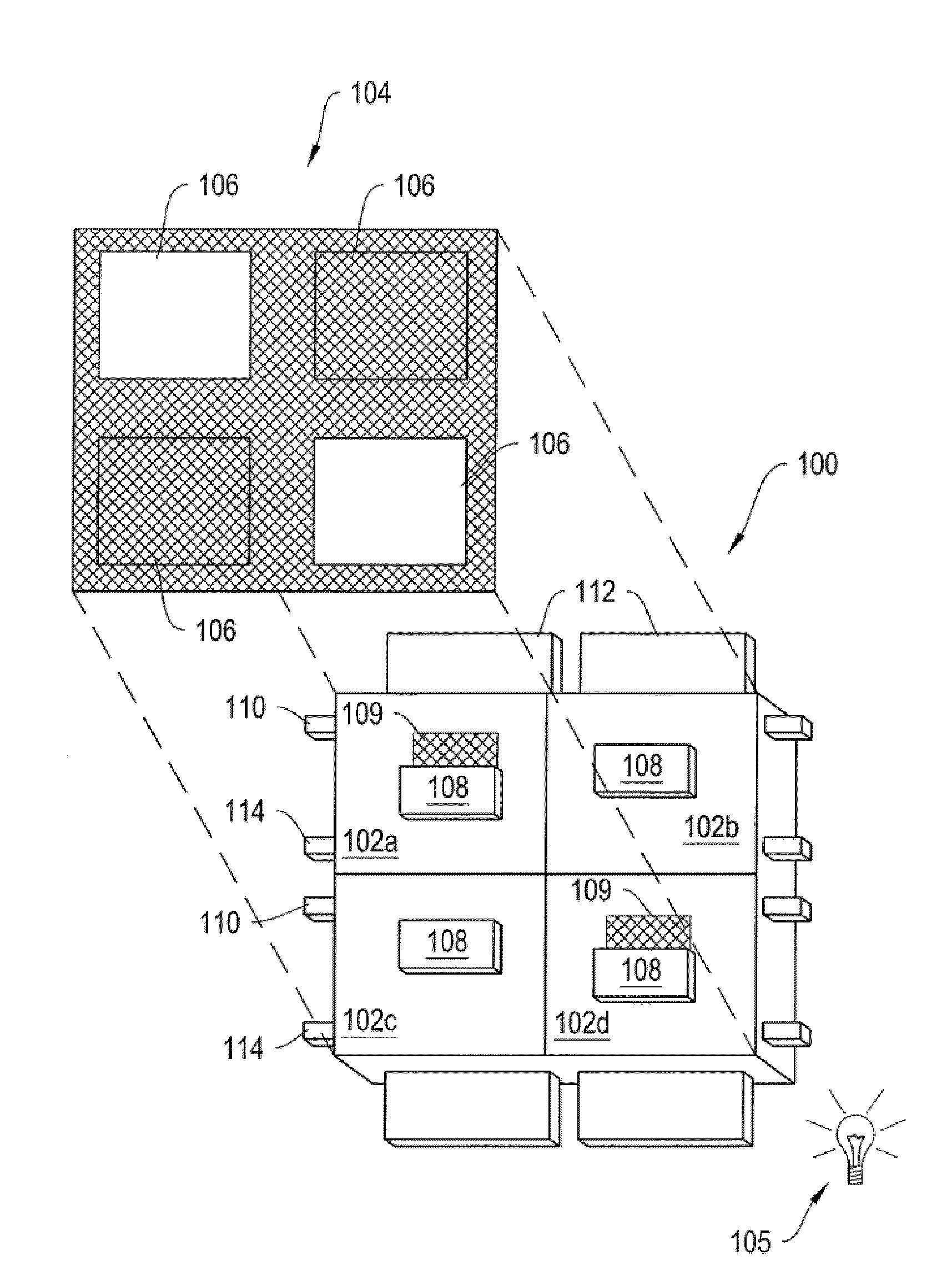
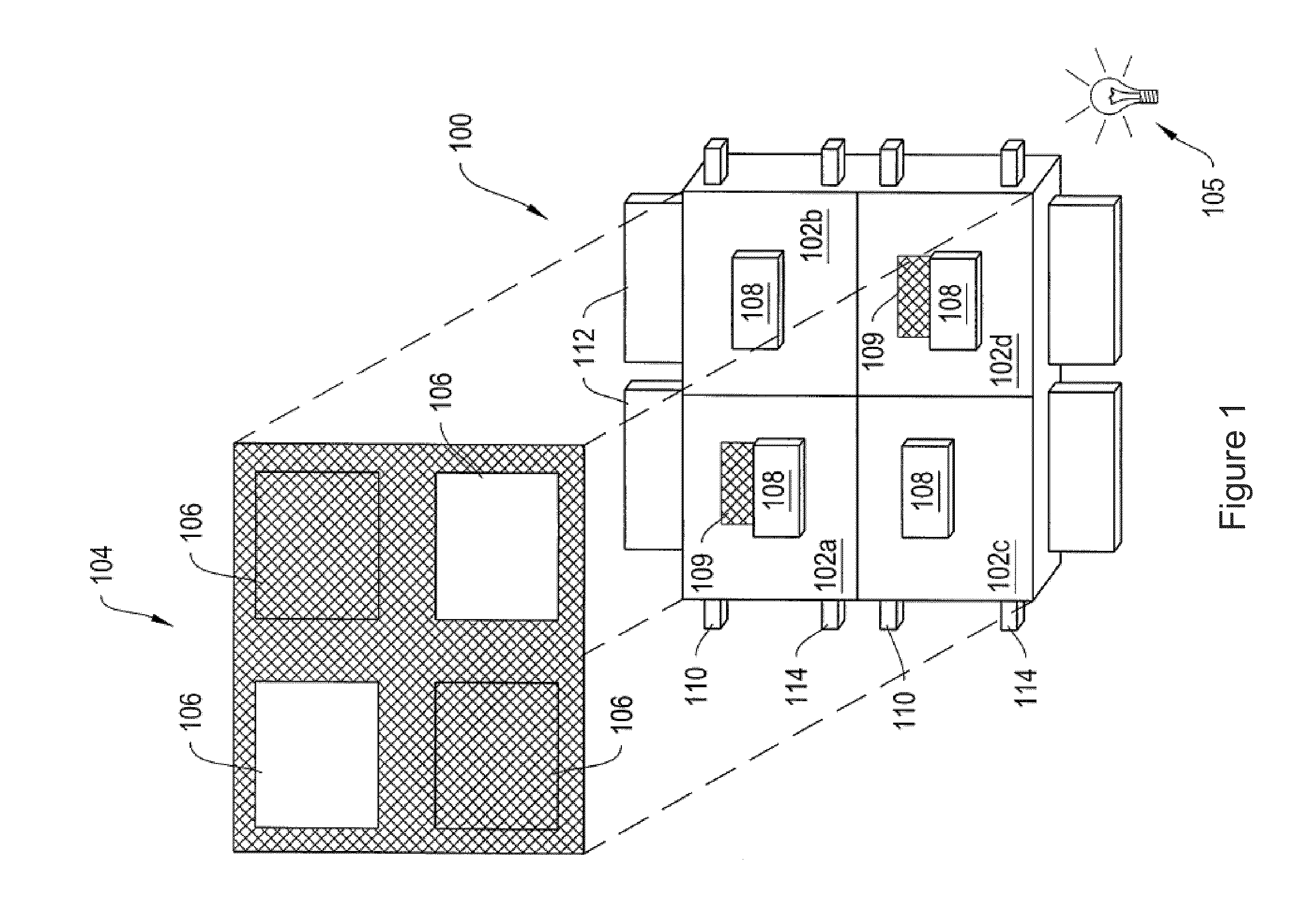
[0033]FIG. 1 is a schematic diagram of a direct-view MEMS-based display apparatus 100, according to an illustrative embodiment of the invention. The display apparatus 100 includes a plurality of light modulators 102a-102d (generally “light modulators 102”) arranged in rows and columns. In the display apparatus 100, light modulators 102a and 102d are in the open state, allowing light to pass. Light modulators 102b and 102c are in the closed sta...


PUM

PropertyMeasurementUnit
Structureaaaaaaaaaa
Widthaaaaaaaaaa
Heightaaaaaaaaaa

Abstract

The invention relates to an improved apparatus and method for the design and manufacture of MEMS anchoring structures for light modulators in order to address the stresses of beams mounted on them.

Description

REFERENCE TO RELATED APPLICATION[0001]This application claims the benefit of U.S. Provisional Patent Application Ser. No. 61 / 108,783, filed on Oct. 27, 2008, entitled “MEMS Anchors”, which is incorporated by reference herein in its entirety.FIELD OF THE INVENTION[0002]The present invention generally relates to the field of displays, such as imaging and projection displays. In particular, the invention relates to the design and manufacture of anchor structures for light modulators to address the deflection of beams mounted on them.BACKGROUND OF THE INVENTION[0003]There is a need in the art for fast, bright, low-powered actuated displays. Displays built from mechanical light modulators are an attractive alternative to displays based on liquid crystal technology. Mechanical light modulators are fast enough to display video content with good viewing angles and with a wide range of color and grey scale. Mechanical light modulators have been successful in projection display applications, ...

Claims


Application Information

Patent Timeline
IPC IPC(8): G02B26/02B22C9/00
CPCB81B1/00B81B2203/0307G02B26/02G02B26/0833B81B3/0035
Inventor WU, JOYCE H.ANDERSSON, MARK B.STEYN, JASPER LODEWYK
Owner SNAPTRACK
Features
  • Generate Ideas
  • Intellectual Property
  • Life Sciences
  • Materials
  • Tech Scout
  • Unparalleled Data Quality
  • Higher Quality Content
  • 60% Fewer Hallucinations
Learn More