Card case

Inactive Publication Date: 2010-05-06
TOKUYAMA KENICHI
View PDF5 Cites 4 Cited by
  • Summary
  • Abstract
  • Description
  • Claims
  • Application Information

AI Technical Summary

Benefits of technology

[0009]A delivery envelope disclosed in Japanese Utility Model Registration No. 3066214 can shield from electromagnetic waves transmitted from the outside when the noncontact IC card is sent to the card user from the card issuer. However, it is not supposed that electromagnetic waves transmitted from the outside are shielded when the card user thereafter carries the noncontact IC card. Accordingly, the card user needs to purchase separately a wallet or a commuter pass holder, which has an electromagnetic waves shielding effect, in order to prevent data from being skimmed or falsified from the outside. Alternatively, the card user needs to separately purchase one card that is disclosed in Japanese Laid-Open Patent Publication 2006-313482 and has an electromagnetic waves shielding effect, and needs to make the card be contained in an existing wallet or a commuter pass holder.
[0010]In consideration of the above-mentioned circumstance, an object of the invention is to provide a card case that can prevent skimming when a noncontact IC card is sent to a card user from an issuer of the noncontact IC card, and can prevent skimming even when the card user carries the noncontact IC card.

Problems solved by technology

Since the noncontact IC card reads and writes data or programs by using electromagnetic waves as described above, there is a problem in that data may be skimmed or falsified from the outside.
Specifically, when the noncontact IC card is sent to a card user from a card issuer by mail, there is a risk that data stored in the IC chip is read out by an external device such as a card reader.
Accordingly, there is a possibility that the data is improperly used.
Accordingly, there is a high possibility that the data on the noncontact IC card could be easily used improperly.

Method used


Image

  • Card case
  • Card case
  • Card case

Examples


first embodiment

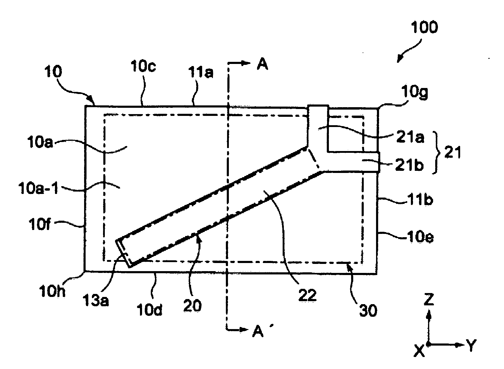
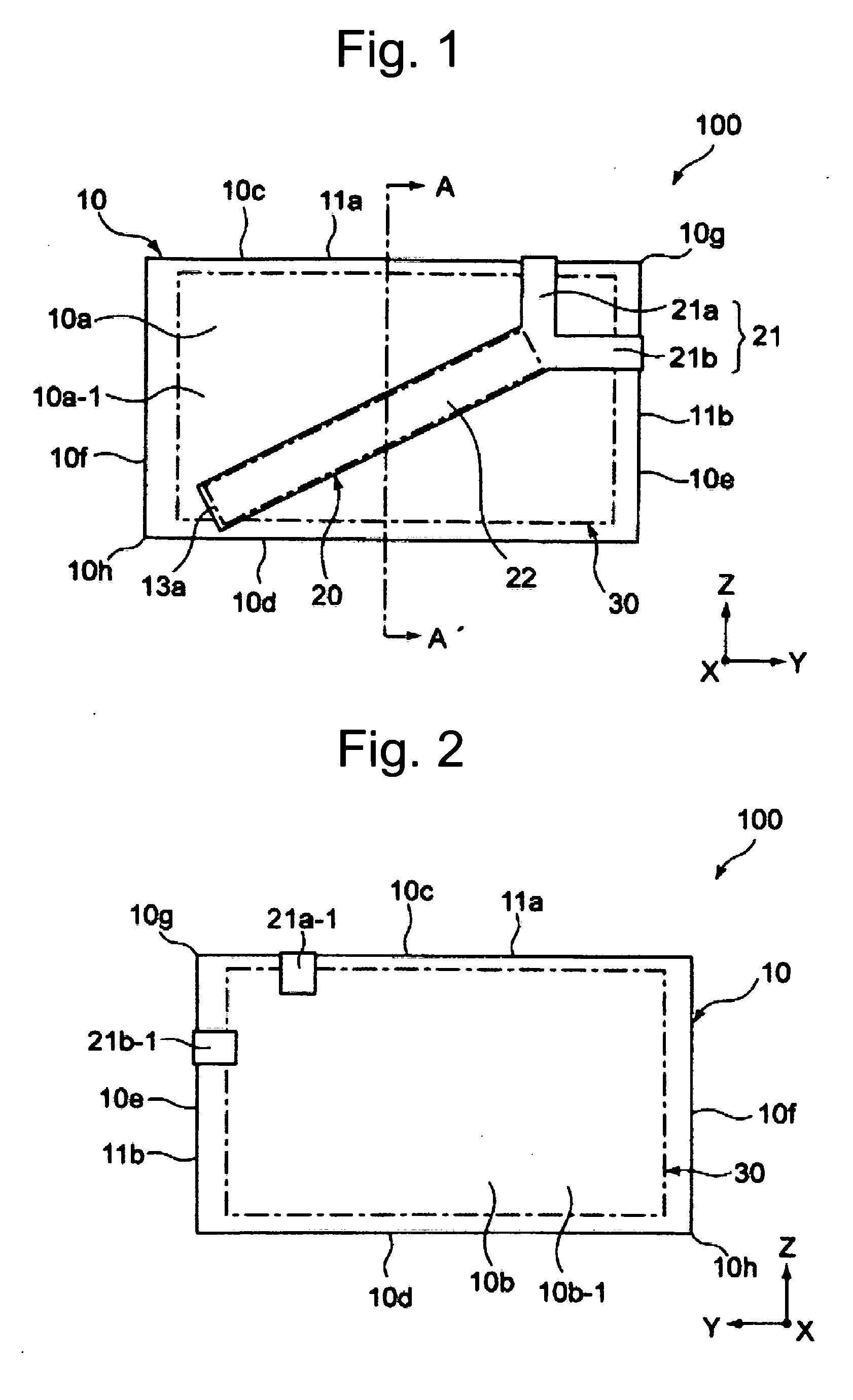
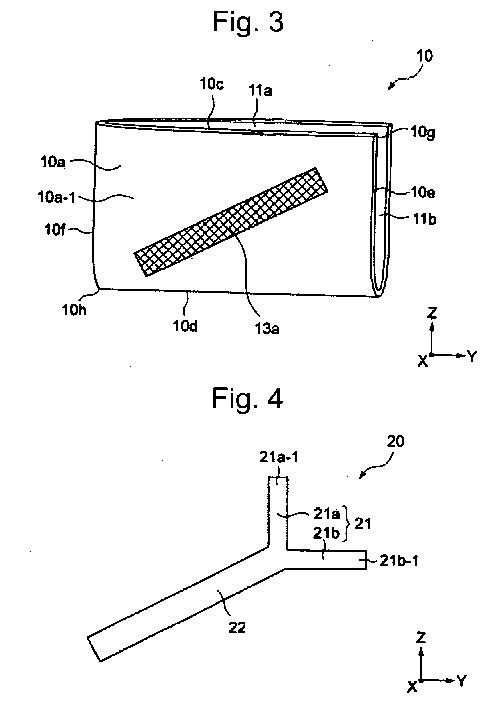
[0052]The first embodiment of the present invention will be described. FIG. 1 is a plan view of a card case according to the first embodiment of the invention, FIG. 2 is a rear view of the card case, FIG. 3 is a perspective view of the card case, FIG. 4 is a development view of a sealing member of the card case, FIG. 5 is a cross-sectional view taken along a line A-A′ shown in FIG. 1, and FIG. 6 is a view showing the internal structure of a noncontact IC card contained in the card case.

[0053]As shown in these drawings, a card case 100 according to this embodiment comprises a case main body 10 and a sealing member 20, and the case main body 10 can contain a noncontact IC card 30.

[0054]The case main body 10 is formed in the shape of a substantially rectangular flat plate. The case main body 10 includes a front member 10a, a rear member 10b, an upper edge portion 10c, a lower edge portion 10d, a right edge portion 10e, and a left edge portion 10f. The front and rear members 10a and 10b...

second embodiment

[0073]The second embodiment of the present invention will be described below. The same members or functions as those of the card case 100 according to the first embodiment are briefly described or not described in the following description, and the difference between the first and second embodiments will be mainly described.

[0074]FIG. 11 is a plan view of a card case according to this embodiment, and FIG. 12 is a rear view of the card case.

[0075]As shown in these drawings, a card case 200 according to this embodiment comprises a case main body 15 and a sealing member 60, and the case main body 15 can contain the noncontact IC card 30.

[0076]In the case main body 15, a front member 15a and a rear member 15b are continuously connected to each other by a lower edge portion 15d, a right edge portion 15e, and a left edge portion 15f. An opening 11c is formed at only an upper edge portion 15c.

[0077]An adhesive section 13b, which has a shape elongated in a direction (Z direction) facing th...

third embodiment

[0082]The third embodiment of the present invention will be described below.

[0083]FIG. 13 is a plan view of a card case according to this embodiment, FIG. 14 is a development view of a sealing member of the card case, and FIG. 15 is a cross-sectional view taken along a line B-B' shown in FIG. 13.

[0084]As shown in these drawings, a card case 300 according to this embodiment comprises the case main body 10 of the first embodiment and a sealing member 70.

[0085]In particular, since the sealing member 70 of this embodiment is different from the sealing member of the above-mentioned first embodiment, the sealing member 70 will be mainly described.

[0086]As shown in the development view of FIG. 14, the sealing member 70 has the form of a tape and includes a peeling section 74, a folded-back section 72, and a sealing section 71.

[0087]The peeling section 74 is detachably attached to the adhesive section 13a so as to cover the adhesive section 13a that is provided on the front surface 10a-1 of...


PUM


Abstract

The present invention provides a card case that can prevent skimming, when a noncontact IC card is sent to a card user from an issuer of it, or carried by the card user. Since metal films, which shield from an electromagnetic wave, are provided in a card main body, it makes prevention of skimming possible, when the noncontact IC card is sent to the card user from the card issuer. The card user peels off a peeling the section by taking off the seal of openings from an adhesive section, and then insert the card main body having the exposed the adhesive section into a card storing section formed in his wallet or commuter pass holder. As a result, skimming of the IC card can be prevented even when it is carried by the card user in his wallet or the commuter pass holder.

Description

RELATED APPLICATION[0001]This application is a continuation of the International Patent Application No. PCT / JP2008 / 001013, filed Apr. 17, 2008, which is based on, and claims priority from, Japan Patent Application 2007-112247, filed Apr. 20, 2007. The disclosures of the prior applications are herein incorporated by reference in their entireties.BACKGROUND OF THE INVENTION[0002]The present invention relates to a card case that can prevent skimming.BACKGROUND ART[0003]In recent years, noncontact IC (Integrated Circuit) cards have been widely employed for tickets of various transportation facilities, electronic money cards, credit cards, employee ID cards, and the like.[0004]The noncontact IC card includes an antenna coil and an IC chip, and reads and writes data or programs between external devices such as a card reader / writer and itself by using electromagnetic waves without contact.[0005]A specific operation is as follows: when the external devices change the magnetic flux, which pa...

Claims


Application Information

Patent Timeline
IPC IPC(8): H05K9/00
CPCA45C1/06A45C11/182A45C2001/065A45C2011/186G06K19/005G06K19/07327G06K19/077G06K19/07749
Inventor TOKUYAMA, KENICHI
Owner TOKUYAMA KENICHI
Why Eureka
Try Eureka