
Orthopedic device

a technology of orthopaedic devices and hinges, applied in the field of orthopaedic devices, can solve the problems of limiting the relative displacement of the hinge, the inability of the force strap and the hinge to work in harmony, and the bulky brace, so as to reduce the effect of medial compartmental or lateral compartmental osteoarthritis, reducing the effect of compartmental osteoarthritis, and minimizing rotational forces

Active Publication Date: 2010-05-06
OSSUR HF
View PDF108 Cites 23 Cited by
  • Summary
  • Abstract
  • Description
  • Claims
  • Application Information

AI Technical Summary

Benefits of technology

[0019]Embodiments of the present invention are described in connection to an improved knee brace and knee bracing method that serve to reduce the effects of either medial compartmental or lateral compartmental osteoarthritis. Embodiments of the knee brace and variations of the knee bracing method reduce the effects of compartmental osteoarthritis by applying multiple forces to the knee on the side remote from the compartment having osteoarthritis while providing forces on the side of the compartment to maintain the brace securely on a leg while minimizing rotational forces. The embodiments of the features described herein are not limited to usage in a knee brace, and may be extended to a variety of orthopedic and prosthetic applications.

Problems solved by technology

Therefore, the force strap and the hinge are found not to be adequately working in harmony.
Moreover, the rigidity of this type of hinge limits the displacement of the hinge relative to the knee.
This results in a bulky brace since a large hinge is required which may extend at least an inch away from the knee.
It has been determined that if more unloading of the knee is required by the brace than is obtained from normal strap tension, and if the force strap is further tightened, the knee is drawn towards the hinge and might strike the hinge.
This results in the hinge applying forces to the knee that counteract the force applied by the force strap.
While known knee braces are successful at reducing pain at or stabilizing a knee joint, many users find these braces to be bulky, difficult to don, complicated to configure, and uncomfortable to wear.

Method used


Image

  • Orthopedic device
  • Orthopedic device
  • Orthopedic device

Examples


Embodiment Construction

A. Overview

[0100]A better understanding of different embodiments of the invention may be had from the following description read in conjunction with the accompanying drawings in which like reference characters refer to like elements.

[0101]While the disclosure is susceptible to various modifications and alternative constructions, certain illustrative embodiments are shown in the drawings and will be described below in detail. It should be understood, however, that there is no intention to limit the disclosure to the specific embodiments disclosed, but on the contrary, the intention is to cover all modifications, alternative constructions, combinations, and equivalents falling within the spirit and scope of the disclosure and defined by the appended claims.

[0102]It will be understood that, unless a term is expressly defined in this patent to possess a described meaning, there is no intent to limit the meaning of such term, either expressly or indirectly, beyond its plain or ordinary m...


PUM


Abstract

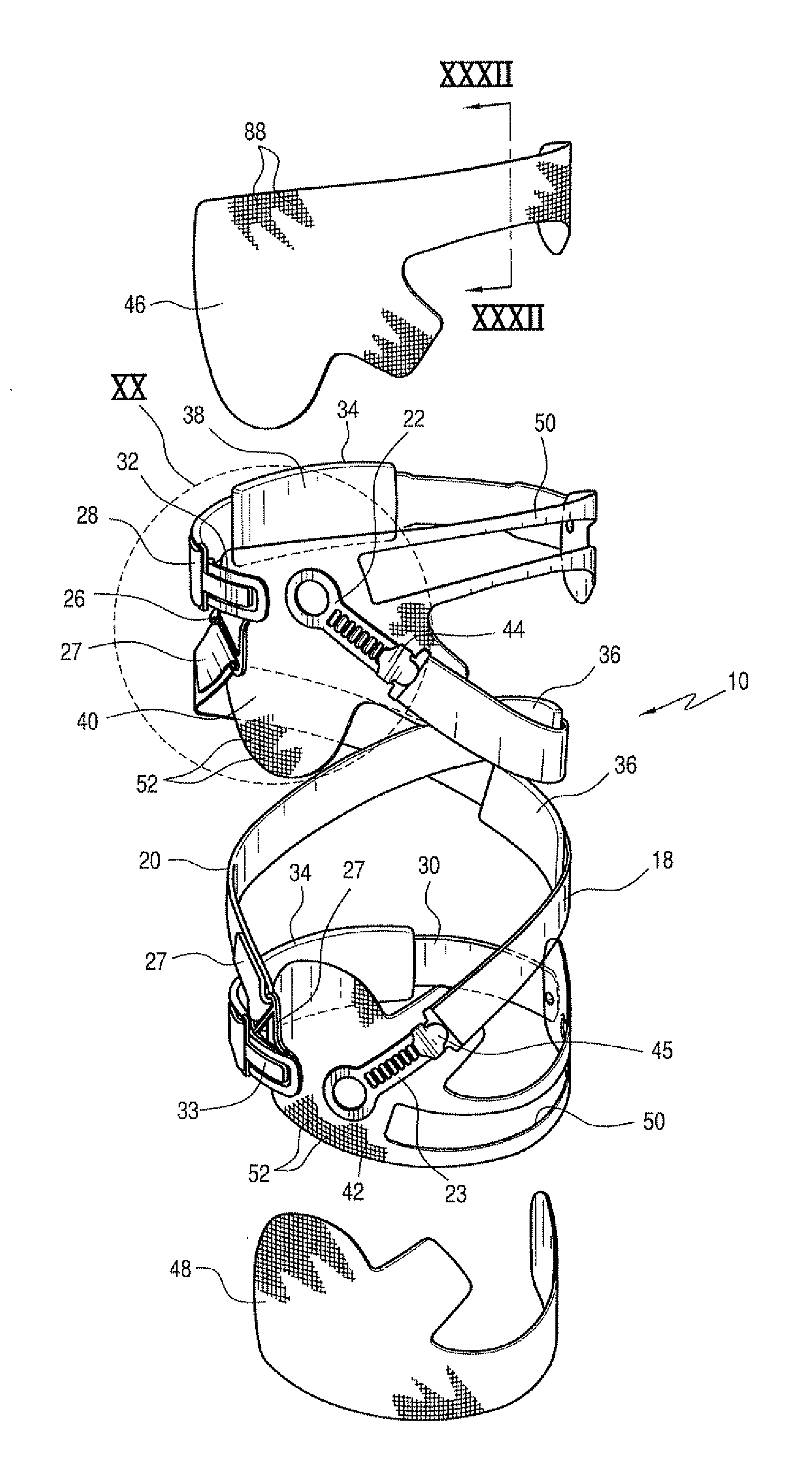
An orthopedic device includes an orthopedic frame, a strap system connected to and depending from the frame and arranged to secure to a limb or joint of a wearer, and a bladder system connected to the strap system. The bladder system has a bladder positioned on the strap system and is arranged between the strap system and the limb or joint of the wearer. The orthopedic device may also include a load cell device connected to the strap system and arranged to monitor pressure exerted on the limb or joint of the wearer, and a tightening mechanism connected to the load cell and arranged to adjust the pressure of the strap system in response to a pressure reading from the load cell. The bladder system and the load cells supplement the strap system to provide for more dynamic support to the limb or joint of the wearer.

Description

CROSS REFERENCE TO RELATED APPLICATIONS[0001]This application is a continuation-in-part of U.S. application Ser. No. 11 / 723,604 Bled on Mar. 21, 2007, which is a continuation-in-part of U.S. application Ser. No. 11 / 312,337 filed on Dec. 21, 2005, which claims the benefit of U.S. provisional application Nos. 60 / 637,754 filed Dec. 22, 2004, 60 / 684,163 filed May 25, 2005, and 60 / 739,407 filed Nov. 25, 2005. All of these noted priority documents are incorporated herein by reference in their entirety.BACKGROUND[0002]A. Background Information on Knee Braces[0003]Knee braces are widely used to treat a variety of knee infirmities. Such braces may be configured to impart forces or leverage on the limbs surrounding the knee joint in order to relieve compressive forces within a portion of the knee joint, or to reduce the load on that portion of the knee. Moreover, in the event that knee ligaments are weak and infirm, a knee brace may stabilize, protect, support, or rehabilitate the knee.[0004]...

Claims


Application Information

Patent Timeline
IPC IPC(8): A61F5/00
CPCA61F5/0123A61F2005/0137A61F2005/0181A61F2005/0174A61F2005/0139
Inventor INGIMUNDARSON, ARNI THOREINARSSON, PALMI
Owner OSSUR HF
Learn More