Assembly of baffles and seals and method of assembling a heat exchanger

a technology of baffles and seals, which is applied in the direction of heat exchanger casings, fixture tubular conduit assemblies, lighting and heating apparatus, etc., can solve the problems of significant cost factors, e.g., sealing, e.g. by kempchen seals, and the optimal arrangement of two-shell-pass heat exchangers

Inactive Publication Date: 2010-05-13
BREMBANA & ROLLE
View PDF4 Cites 12 Cited by
  • Summary
  • Abstract
  • Description
  • Claims
  • Application Information

AI Technical Summary

Benefits of technology

[0016]Applicant has realized that reliable sealing between two spaced apart longitudinal baffles in a multi-pass heat exchanger can be obtained if a wall member is provided that forms a double wall with the heat exchanger shell, and wherein the longitudinal seal is provided between the wall member and the heat exchanger shell. In this way an optimum position on the wall member can be chosen for the longitudinal seal, and / or the geometry between the seal and the shell can be can be optimised. Only one seal can be sufficient for sealing two edges of longitudinal baffles against the shell.
[0024]In a special embodiment tubes extend from a tube sheet through the transverse baffles and an transverse end baffle to a tube end sheet, and the wall members are connected at one end to the tube sheet and at the other end to the end baffle. Preferably then the end baffle is provided with a seal so as to prevent bypass of fluid between shell passes around the end baffle.

Problems solved by technology

In many cases a two-shell-pass heat exchanger is not an optimal arrangement.
However, this is not done in practice, as reliable sealing of two longitudinal baffles poses practical problems.
Due to this unusual geometry, sealing, e.g. by Kempchen seals, is seen as problematic.
Also, seals such as Kempchen seals represent a significant cost factor, and for a three-pass arrangement four longitudinal seals would be required.

Method used


Image

  • Assembly of baffles and seals and method of assembling a heat exchanger
  • Assembly of baffles and seals and method of assembling a heat exchanger
  • Assembly of baffles and seals and method of assembling a heat exchanger

Examples


Embodiment Construction

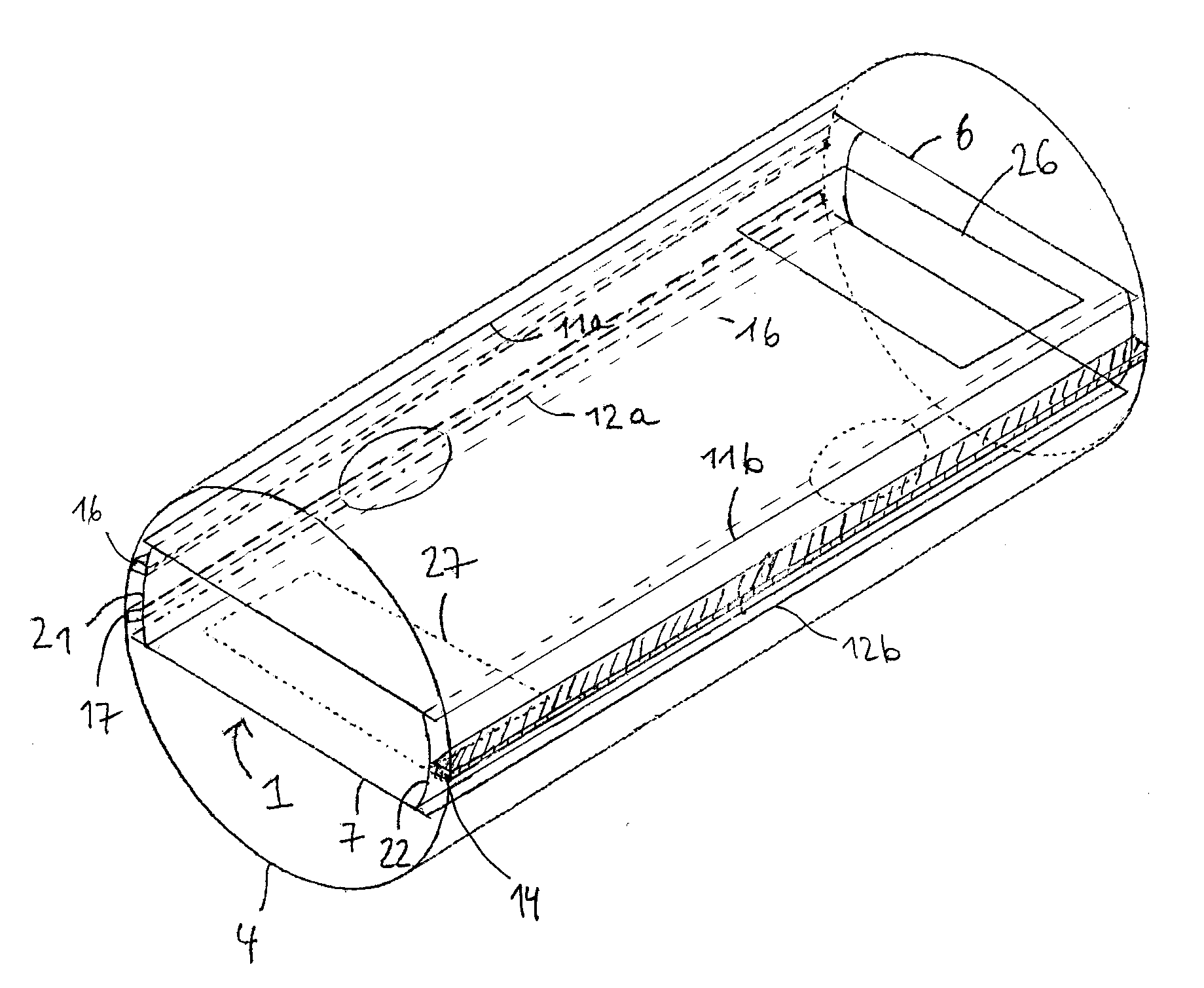
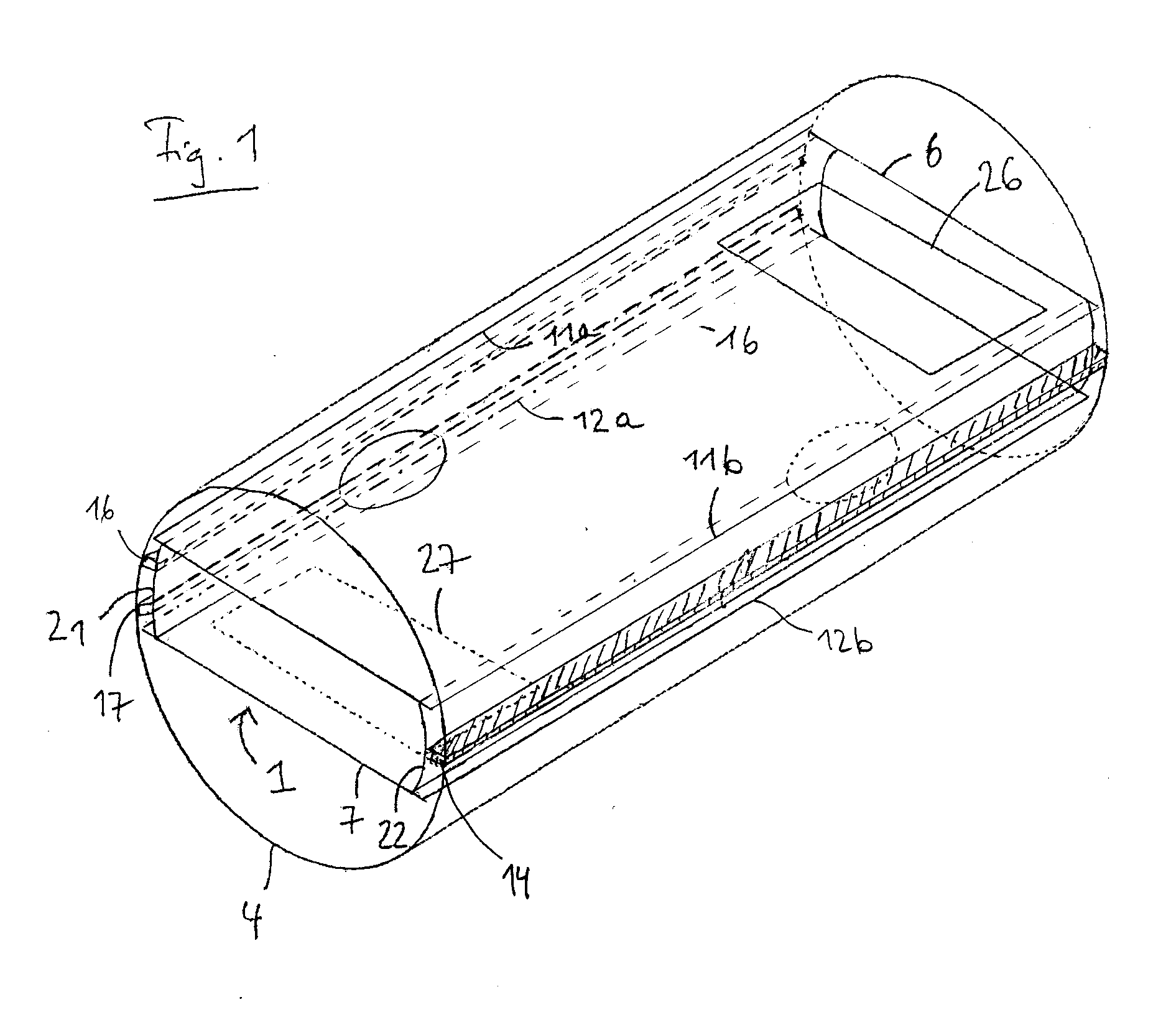
[0043]FIG. 1 shows schematically a three-dimensional view of an assembly 1 of baffles and seals according to the present invention. For the sake of clarity part of a heat exchanger shell 4 is indicated around the assembly, but it will be understood that the shell 4 does in general not need to form part of the assembly.

[0044]The assembly comprises two spaced apart longitudinal baffles 6,7 each having a pair of longitudinal rims 11a,b;12a,b and dividing the interior space of the heat exchanger 1 into three compartments. The assembly further comprises wall members 21 and 22 that extend between the longitudinal baffles 6,7, near rims 11a,12a; and 11b,12b, respectively. The wall members form a double wall with the heat exchanger shell 4 after mounting, and represent the longitudinal transverse walls of the middle compartment of the heat exchanger 1 For the sake of illustration of two embodiments, wall member 22 is provided with one longitudinal seal 14, and wall member 21 is provided wit...


PUM

PropertyMeasurementUnit
widthaaaaaaaaaa
angleaaaaaaaaaa
angleaaaaaaaaaa

Abstract

An assembly (1) of baffles and seals for mounting in a heat exchanger shell (4), which assembly (1) comprises a plurality of longitudinal baffles (6,7); at least one longitudinal seal (14,16,17), wherein the assembly (1) further comprises a wall member (21, 22) that is arranged to extend between spaced apart longitudinal baffles (6,7) so as to form a double wall with the heat exchanger shell (4) after mounting, and wherein the at least one longitudinal seal (14,16,17) is arranged on the wall member (21, 22) and away from the longitudinal baffles (6,7) so as to sealingly engage the wall member (21, 22) against the heat exchanger shell (4) after mounting.

Description

FIELD OF THE INVENTION[0001]The present invention relates to an assembly of baffles and seals and to its use in a method of assembling a heat exchanger.BACKGROUND OF THE INVENTION[0002]A shell-and-tube heat exchanger is an indirect heat exchanger. Heat is transferred between a fluid passing through the tubes of a tube bundle (the tube side) extending in the heat exchanger shell, and a fluid passing through the space outside the tubes (the shell side). Details of the shell-and-tube heat exchangers can for example be found in Perry's Chemical Engineers' Handbook, 6th edition, 1984, McGraw-Hill Inc., page 11-3 to 11-21.[0003]A particular type of heat-exchanger known as two-shell-pass heat exchanger has been developed for improved transfer of heat in a given shell size. In this type of heat exchanger a generally cylindrical outer tube is provided internally with an axially and longitudinally extending partition baffle. Such shell types include the two-pass shell with longitudinal baffle...

Claims


Application Information

Patent Timeline
Patent Type & Authority Applications(United States)
IPC IPC(8): F28F9/22B21D53/02B23P11/00
CPCF28D7/1607F28F9/005Y10T29/4935F28F2009/224Y10T29/49826F28F9/22F28D7/00
Inventor MULDER, DOMINICUS FREDERICUS
Owner BREMBANA & ROLLE
Why Eureka
Try Eureka