Fire alarm and like devices

a technology of fire alarms and like devices, applied in the field of fire alarms, can solve the problems of user difficulty in operating the alarm, easy mounting in the wrong orientation, false sense of security for people,

Inactive Publication Date: 2010-05-13
FIREANGEL
View PDF11 Cites 16 Cited by
  • Summary
  • Abstract
  • Description
  • Claims
  • Application Information

AI Technical Summary

Benefits of technology

[0016]The mounting assembly may include a generally planar mounting plate having an upper surface and a through-opening for receiving a fixing such as a screw for fixing the mounting assembly to a generally flat surface, the through-opening being elongate and having an enlarged portion for passage of a head of the fixing through the through-opening, a narrowed portion for retention of the head and a neck portion therebetween. The neck portion may define a wall portion, the wall portion being formed by a tongue, the tongue being adapted to resile away from the opposing wall of the neck portion thereby to allow passage of the fixing from the enlarged portion to the narrowed portion, and to prevent passage of the fixing from the narrowed portion to the enlarged portion.

Problems solved by technology

In addition, because the battery is normally clipped onto a terminal holder it can easily be mounted in the wrong orientation.
Both of these conditions provide a false sense of security to people seeing the alarm and believing it to be operational when in fact it is not.
In addition where the alarm is a multi functional device there are usually one or a number of buttons for the different functions and operations of the alarm and the user may have difficulty in operating the alarm.
This problem is present when the alarm is new as few people tend to read instruction manuals.
The problem is exacerbated when dealing with a second user of an alarm where it is likely that the manual has been misplaced or discarded.
The above are some of the problems that can be encountered with these types of alarms and which have an effect on the usefulness of the alarms.
These all relate to the action of the user or the ability of the user to bypass the operation of the device in a deceptive and potentially dangerous manner.

Method used


Image

  • Fire alarm and like devices
  • Fire alarm and like devices
  • Fire alarm and like devices

Examples


Embodiment Construction

[0028]Reference will now be made in detail to the construction and operation of preferred implementations of the present invention illustrated in the accompanying drawings. The following description of the preferred implementations of the present invention is only exemplary of the invention. The present invention is not limited to these implementations, but may be realized by other implementations. Indeed, In the below-described embodiment, the invention is described in relation to a smoke alarm. It will be appreciated, however, that the invention is equally applicable to an alarm for detecting other air pollutants and noxious and toxic gases such as carbon monoxide, radon or the like, or any forms of radiation.

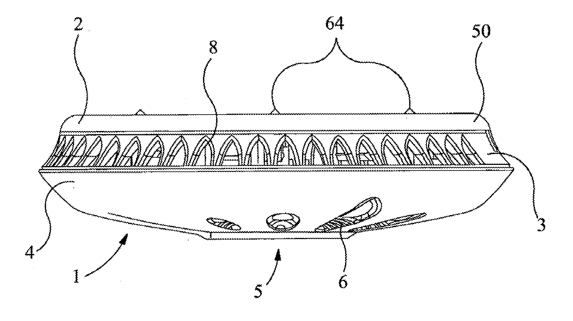
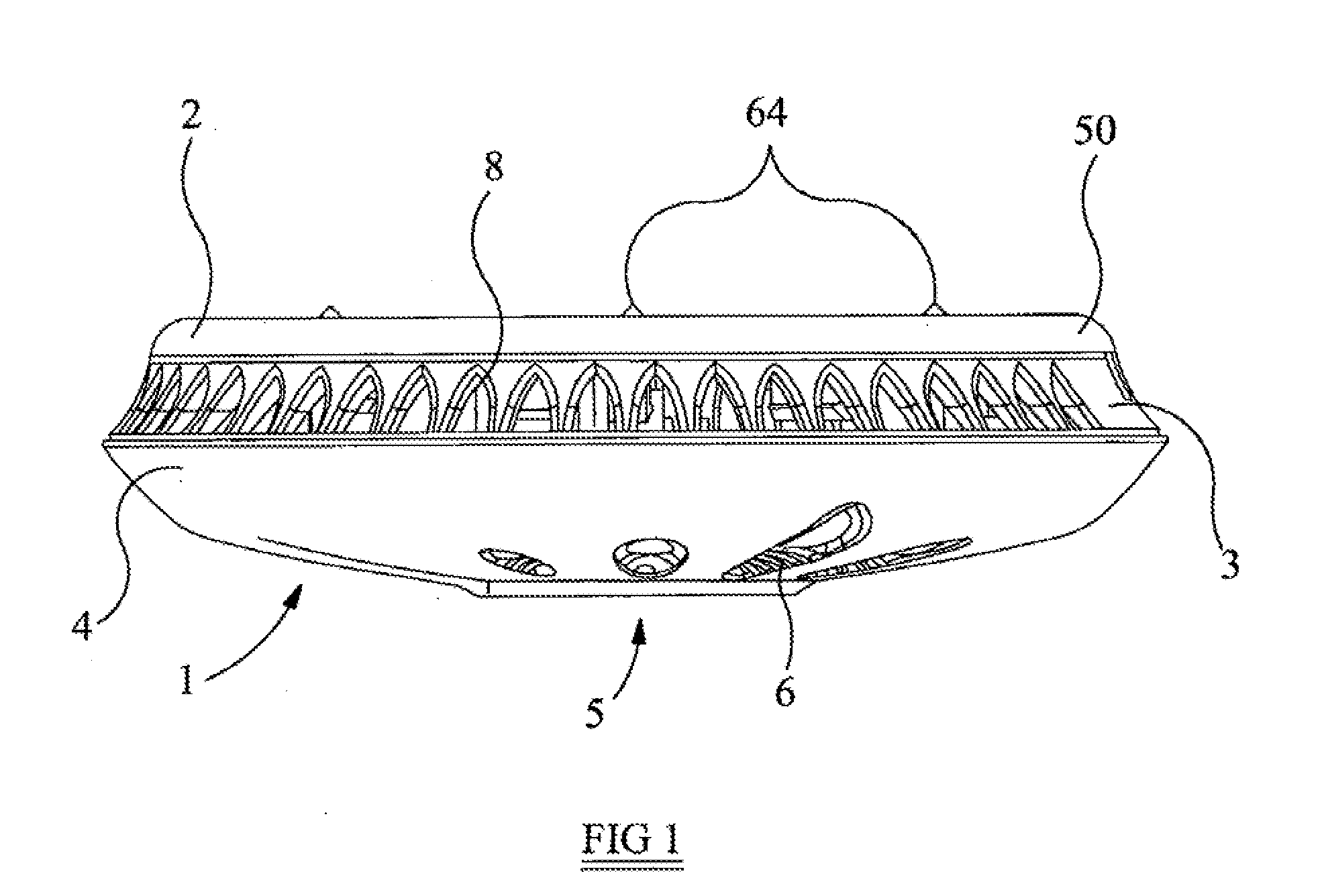
[0029]Referring to the drawings, FIG. 1 shows a side view of a preferred form of alarm 1 according to the invention. The alarm is suitable for mounting to a flat surface such as a wall or ceiling but is described here in relation to its mounting to a ceiling. Certain aspects ...


PUM


Abstract

An alarm for detecting radiation and/or pollutants such as smoke, carbon monoxide or the like has a housing, a mounting plate for mounting the housing to a flat surface, cooperating means on the housing and the mounting plate engageable to secure the housing to the mounting plate, and an alarm circuit including a detector for detecting the radiation and/or pollutants. The alarm also has a switch in the alarm circuit in the housing and a magnet on the mounting plate, the arrangement being such that the magnet actuates the switch in response to engagement of the housing with the mounting plate thereby to arm the circuit. A battery compartment in the housing receives a battery for the alarm and stop means prevent proper engagement of the cooperating means in the absence of the battery. The mounting plate is generally planar having an upper surface and a through-opening for receiving a fixing such as a screw for fixing the mounting plate to a generally flat surface. The through-opening is elongate having an enlarged portion for passage of the head of the fixing through the through-opening, a narrowed portion for retention of the head and a neck portion therebetween. The alarm circuit also preferably includes actuation means configured to scroll through the various functions of the alarm when the actuation means is activated in a particular fashion.

Description

BACKGROUND OF THE INVENTION[0001]1. Field of the Invention[0002]This invention relates to an alarm for detecting radiation, carbon monoxide, smoke and / or other air pollutants comprising particularly for use in a household environment.[0003]2. Description of the Prior Art and Related Information[0004]A typical conventional alarm is battery-powered and is intended to be fitted directly to a flat surface, such as a ceiling, by means of screws or the like which pass through the housing of the alarm. The alarm is usually provided with a removable cover, or a cover that pivots away to the side so that access can be gained to the housing interior to change the battery. The battery is commonly mounted by simply clipping onto a terminal pad.[0005]Therefore the user can close the cover without a battery in place. In addition, because the battery is normally clipped onto a terminal holder it can easily be mounted in the wrong orientation. Both of these conditions provide a false sense of secur...

Claims


Application Information

Patent Timeline
Patent Type & Authority Applications(United States)
IPC IPC(8): G08B17/12
CPCG08B17/00G08B17/113
Inventor RUTTER, NICHOLAS ALEXANDERHART, STUART ARTHUR
Owner FIREANGEL
Why Eureka
Try Eureka