
Speed warning method and apparatus for navigation system

a technology of speed warning and navigation system, applied in the direction of external condition input parameters, instruments, transportation and packaging, etc., can solve the problems of not only threatening the lives of drivers and passengers in vehicles, but also the lives of pedestrians, other vehicles, and drivers who fail to drive under speed limits. , to achieve the effect of convenient interfa

Inactive Publication Date: 2010-05-13
ALPINE ELECTRONICS INC
View PDF7 Cites 26 Cited by
  • Summary
  • Abstract
  • Description
  • Claims
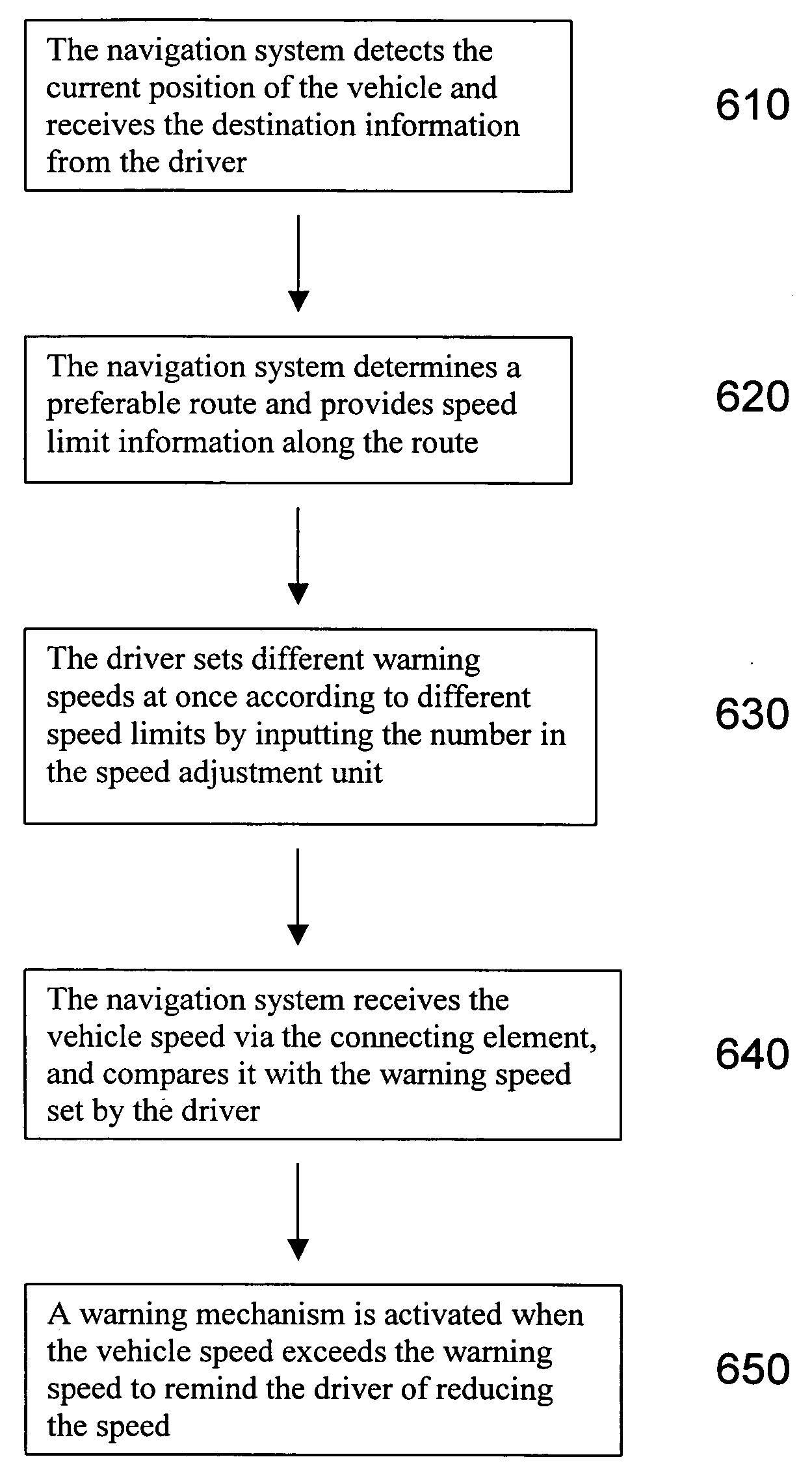
  • Application Information

AI Technical Summary

Benefits of technology

[0008]It is, therefore, an object of the present invention to provide a speed warning method and apparatus to be implemented in combination with a navigation system for achieving a convenient interface for the driver to set a threshold speed for generating a warning regarding the speed limit depending upon a particular location where a vehicle is running.
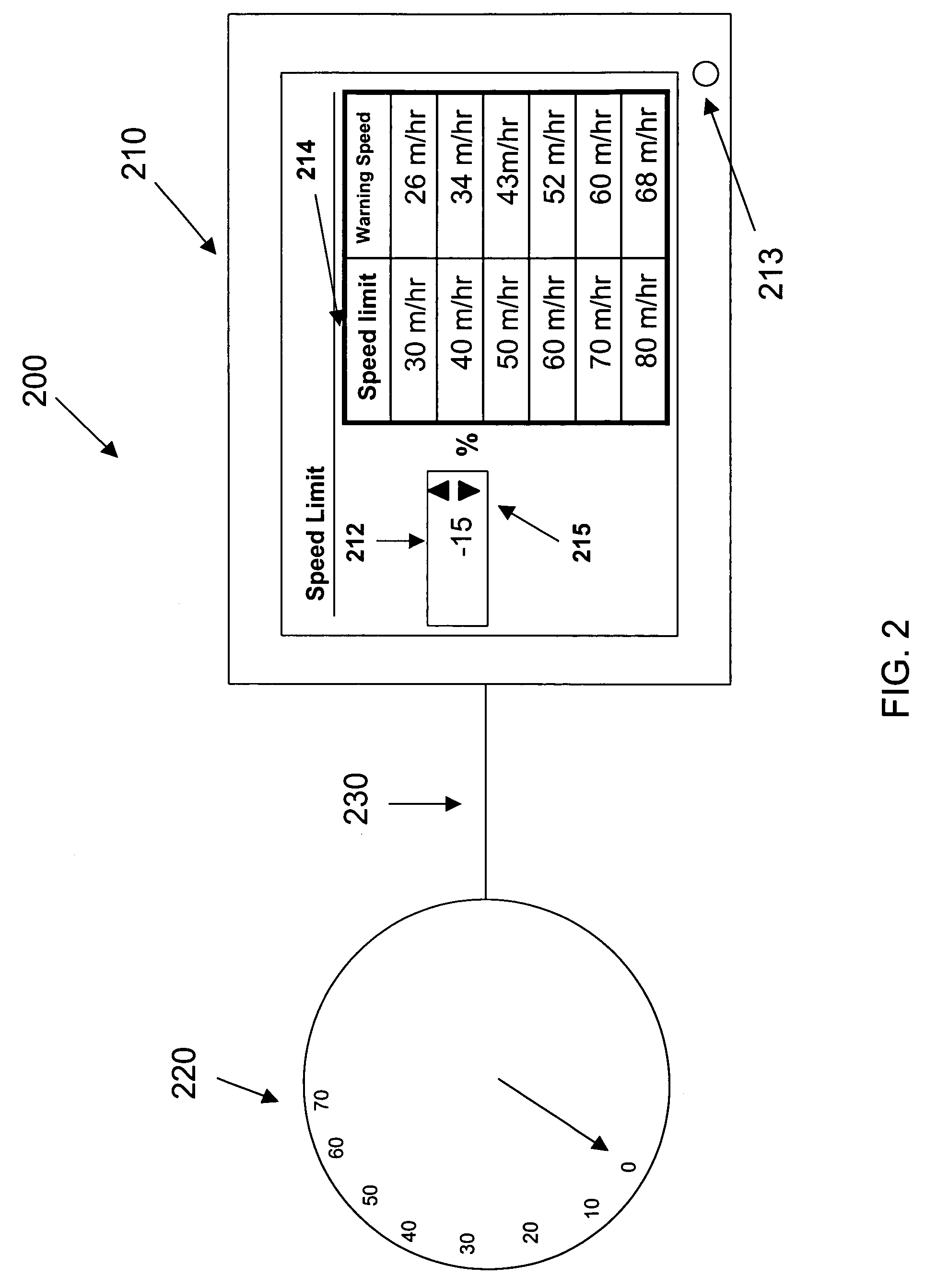
[0009]Namely, the present invention relates to a method and an apparatus for providing a warning regarding a vehicle speed to a driver when the vehicle speed exceeds the threshold speed. More specifically, the present invention allows the driver to set the threshold level for generating a warning regarding the vehicle speed which is slightly higher or lower than the posted speed limit based on the user's driving style and preference. For example, if the user likes to drive slowly, the warning threshold of the vehicle speed can be set even lower than the posted speed limit. On the other hand, the driver can also set the warning threshold of the vehicle speed higher than the speed limit, for example, within an acceptable error range of speedometer. In the latter case, however, the driver should pay attention to the speeding enforcement tolerance to avoid traffic citations and penalties.
[0010]The present invention is especially advantageous when the driver travels to several different areas with different speed limits. The present invention provides a simple and convenient interface for the driver not only to receive speed limit information along the route, but also to set different threshold levels of the vehicle speed for producing the warning according to different speed limits at once. Thus, the driver does not have to modify the threshold speed for generating the warning repeatedly when encountering different speed limits. Since the driver only has to set the threshold speed for generating the warning once, the “driver distraction” during the driving can be significantly reduced or minimized and the driver can be much more focused on operating the vehicle.

Problems solved by technology

Safety is always the most important concern in vehicle driving, and speeding is one of the common causes of traffic accidents.
Since high speed usually reduces the possibility to respond in time for drivers, accidents are more likely to occur at higher speed.
Speeding not only threatens the lives of the driver and passenger in a vehicle, but also the lives of people in other vehicles and pedestrians nearby.
However, drivers sometimes fail to drive under speed limit because they either do not know the speed limit in certain areas, or do not pay attention to it.
If there are several different speed limits along the route, it may be dangerous to take the driver's eyes out of the road because the driver has to pay attention to different speed limits and record them into the navigation system.
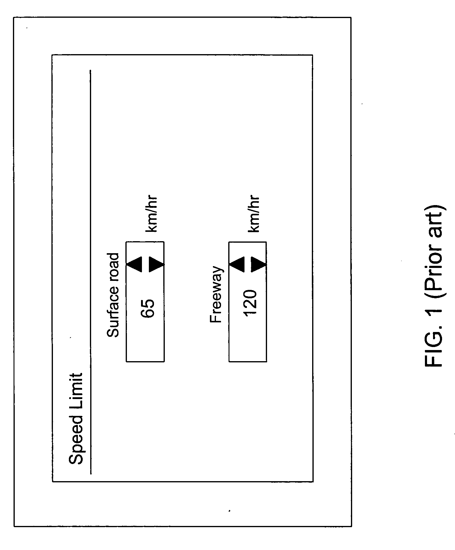
However, this conventional technology does not allow the driver to slightly modify the speed limit along the route.
For example, if the driver would like to drive slower, he or she may want to customize the speed limit ten percent below the legal limit, which is not possible by the conventional technology.
However, similar to the '074 to Cuozzo noted above, this conventional technology does not allow the driver to slightly modify the speed limit along the route.

Method used


Image

  • Speed warning method and apparatus for navigation system
  • Speed warning method and apparatus for navigation system
  • Speed warning method and apparatus for navigation system

Examples


Embodiment Construction

[0023]The detailed description set forth below is intended as a description of the presently exemplary device provided in accordance with aspects of the present invention and is not intended to represent the only forms in which the present invention may be prepared or utilized. It is to be understood, rather, that the same or equivalent functions and components may be accomplished by different embodiments that are also intended to be encompassed within the spirit and scope of the present invention.

[0024]Unless defined otherwise, all technical and scientific terms used herein have the same meaning as commonly understood to one of ordinary skill in the art to which this invention belongs. Although any methods, devices and materials similar or equivalent to those described can be used in the practice or testing of the invention, the exemplary methods, devices and materials are now described.

[0025]All publications mentioned are incorporated by reference for the purpose of describing and...


PUM


Abstract

A method and apparatus allows the driver to set a threshold speed for generating a warning by slightly modifying the speed limit, such that a warning mechanism can be activated when the vehicle speed exceeds the threshold speed. The method and apparatus achieves a convenient interface for the driver to set the threshold speeds at once according to different speed limits by setting a number such as a percentage in a speed adjustment unit. The number indicates the difference in percentage between the speed limit and the threshold speed. The threshold speed can be either higher or lower than the speed limit based on the driving style and preference of the driver.

Description

FIELD OF THE INVENTION[0001]This invention relates to a speed limit warning apparatus and method, and more specifically, to a speed limit warning apparatus and method to be implemented in combination with a navigation system for achieving a convenient interface for the driver to set a threshold speed for generating a warning regarding the speed limit depending upon particular locations where a vehicle is running.BACKGROUND OF THE INVENTION[0002]Safety is always the most important concern in vehicle driving, and speeding is one of the common causes of traffic accidents. Since high speed usually reduces the possibility to respond in time for drivers, accidents are more likely to occur at higher speed. Speeding not only threatens the lives of the driver and passenger in a vehicle, but also the lives of people in other vehicles and pedestrians nearby.[0003]In order to avoid speeding and remind drivers of the maximum speed allowed by law, the government sets different speed limits in dif...

Claims


Application Information

Patent Timeline
IPC IPC(8): G06F19/00B60Q1/00
CPCB60W30/146B60W2550/402B60W2550/22B60W2555/60B60W2556/50
Inventor PHAM, DON
Owner ALPINE ELECTRONICS INC
Learn More