
Back Support System

Inactive Publication Date: 2010-05-20
HURLEY PATRICK TIMOTHY
View PDF6 Cites 14 Cited by
  • Summary
  • Abstract
  • Description
  • Claims
  • Application Information

AI Technical Summary

Benefits of technology

[0024]This invention is a back support system designed to reduce the stress exerted on the back of a wearer when he bends over to lift a load. This back support system comprises a harness which is secured to the torso of the wearer, by means of breast straps joined at the front of the wearer's chest. The harness also comprises two shoulder straps wrapped from front to back, over the shoulders of the wearer.
[0028]The back support system generates a tension force when said wearer bends over to lift a load. This tension force counterbalances the force generated on the back of the wearer by the load, thereby relieving stress on his back. In addition, the tension system, maintains the tensile force essentially aligned along the bone structure of the leg of the wearer thereby relieving stress along his legs.
[0029]This invention includes several variations such as fastening and adjusting buckles to fit wearer's of different sizes. The curved rails can be made with an upper surface concave in the perpendicular direction of the rail. The concavity could be obtuse or extreme such as to form a tube slotted along the length of the rail. The elastic cable could be made of surgical tubing configured such that the ends of the tubing are joined together to form a loop. The surgical tubing may be reinforced at their point of contact with the tension straps and with the legging nets by rigid u-shaped tubing. Carabiners could be used to join the elastic cable to the legging nets. Fastening and adjusting buckles may be replaced by VELCRO™ fasteners. D-shaped rings can be used to keep the tension straps firmly inside the rails. A horizontal strap can be used to join together the tension straps to prevent them for sliding off the rails.

Problems solved by technology

Back injuries that result from bending at the waist and lifting heavy loads, besides being painful, difficult and costly to treat, cause the loss of millions of dollars in productivity.
As a result tremendous forces are exerted on the vertebras and may cause injuries.
The prior art does not address in a methodical, well thought out engineering approach, the problem of how to design a back support system that distributes tensile and compressive forces such as to minimize stress on the spinal column and on soft tissues.

Method used


Image

  • Back Support System
  • Back Support System
  • Back Support System

Examples


Embodiment Construction

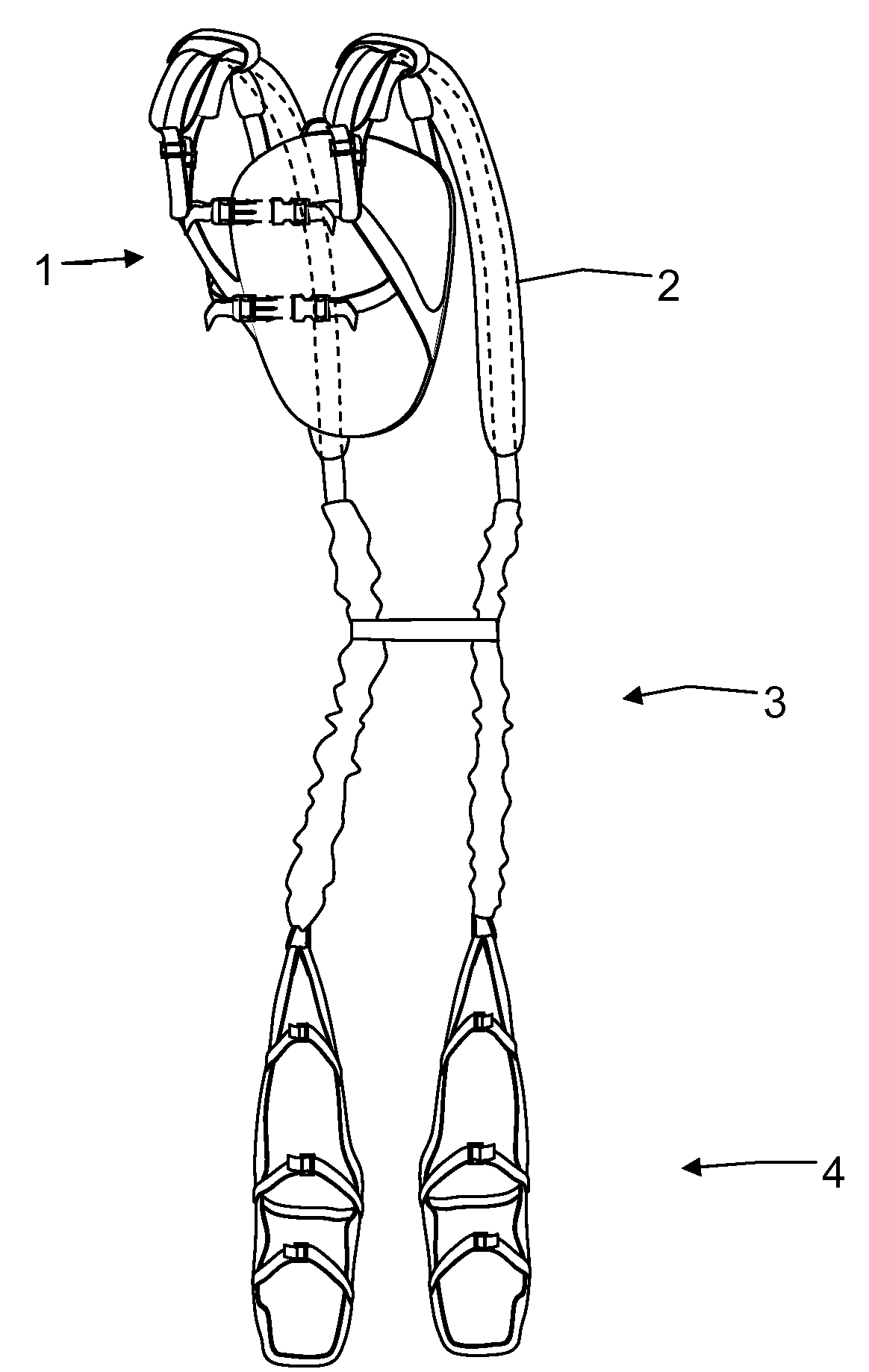
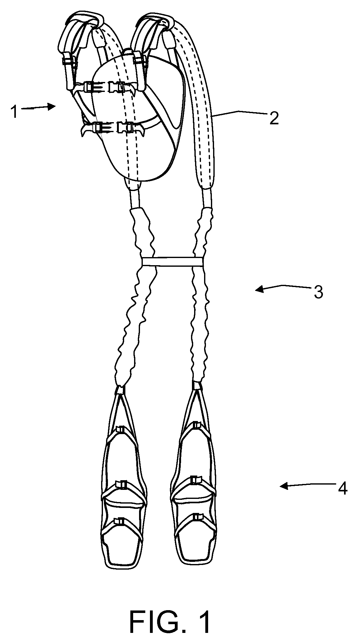
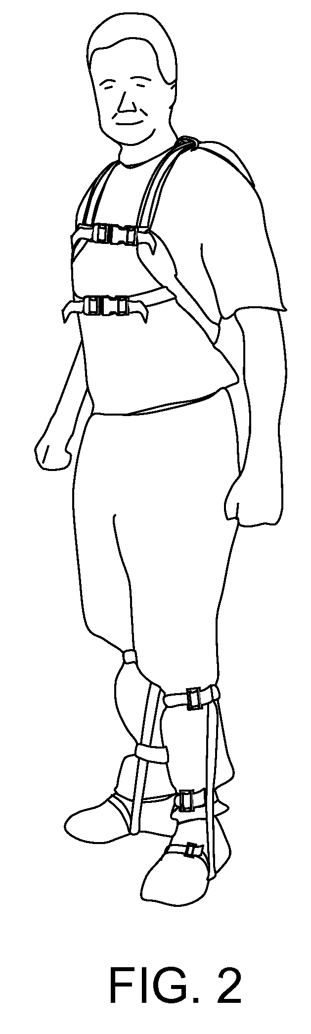
[0030]This invention is illustrated in FIG. 1. FIGS. 2 and 3 illustrate the device as it is worn by a person. It comprises the following parts

[0031]a) The harness 1

[0032]b) The yoke system 2

[0033]c) The tension system 3

[0034]d) The legging strap system 4

[0035]Harness

[0036]This component is shown in FIG. 4. It resembles to a certain extent, a back-pack harness. It is made of a flexible, breathable mesh material attached to the chest of the wearer. Two padded shoulder straps 11 wrap over the shoulder of the wearer. These straps are equipped with adjusting buckles 12. Two additional straps 13 and 34 wrap around the chest of the wearer and are attached to the shoulder straps approximately at the breast location on the chest. These straps are equipped with adjusting and fastening buckles 14 and 41.

[0037]Yoke System

[0038]The yoke system 2 is shown in FIG. 5. It consists of two rigid curved rails 15 attached to the shoulder straps 11 and wrapping around the shoulders of the wearer. The two...


PUM


Abstract

This invention is a back support system designed to reduce the stress exerted on the back of a wearer when he bends over to lift a load. This back support system comprises a harness and a yoke for distributing the load on the shoulder of the wearer. The back support also comprises a tension system equipped with elastic cables. The back support further comprises leggings including straps designed to wrap around the sole of the wearer and to maintain the force acting on the leg as close as possible to the bone structure of the leg of the wearer, thereby relieving stress on his back and along his legs.

Description

FIELD OF THE INVENTION[0001]The present invention relates to equipment for supporting, strengthening the back and reducing back strain in circumstances requiring bending at the waist. It also relates to equipment designed to prevent back injuries during bending or lifting activities.BACKGROUND[0002]Back injuries that result from bending at the waist and lifting heavy loads, besides being painful, difficult and costly to treat, cause the loss of millions of dollars in productivity. These injuries are caused by high twisting forces exerted on the spinal column by the cantilevered action of bending. The vertebras which occupy a few square inches of surface operate as a fulcrum in a lever system. The short segment of the lever system is located on the vertebras themselves. The long segment of the lever system includes the arms, the hands and the load itself. Therefore the force applied to this lever may be located feet away from the backbone. As a result tremendous forces are exerted on...

Claims


Application Information

Patent Timeline
IPC IPC(8): A61F5/00A61F5/02
CPCA61F5/026
Inventor HURLEY, PATRICK TIMOTHY
Owner HURLEY PATRICK TIMOTHY
Features
  • Generate Ideas
  • Intellectual Property
  • Life Sciences
  • Materials
  • Tech Scout
  • Unparalleled Data Quality
  • Higher Quality Content
  • 60% Fewer Hallucinations
Learn More