Drill and flavored fluid particles combination

a technology of fluid particles and flavored fluids, applied in the field of medical drilling techniques, can solve the problems of inability to adapt to the and the prior art use of water in cutting and drilling operations

Inactive Publication Date: 2010-05-20
BIOLASE TECH INC
View PDF99 Cites 12 Cited by
  • Summary
  • Abstract
  • Description
  • Claims
  • Application Information

AI Technical Summary

Problems solved by technology

The use of water in these prior art systems has been somewhat successful for the limited purposes of cooling a target surface or removing debris therefrom.
These p

Method used


Image

  • Drill and flavored fluid particles combination
  • Drill and flavored fluid particles combination

Examples


Embodiment Construction

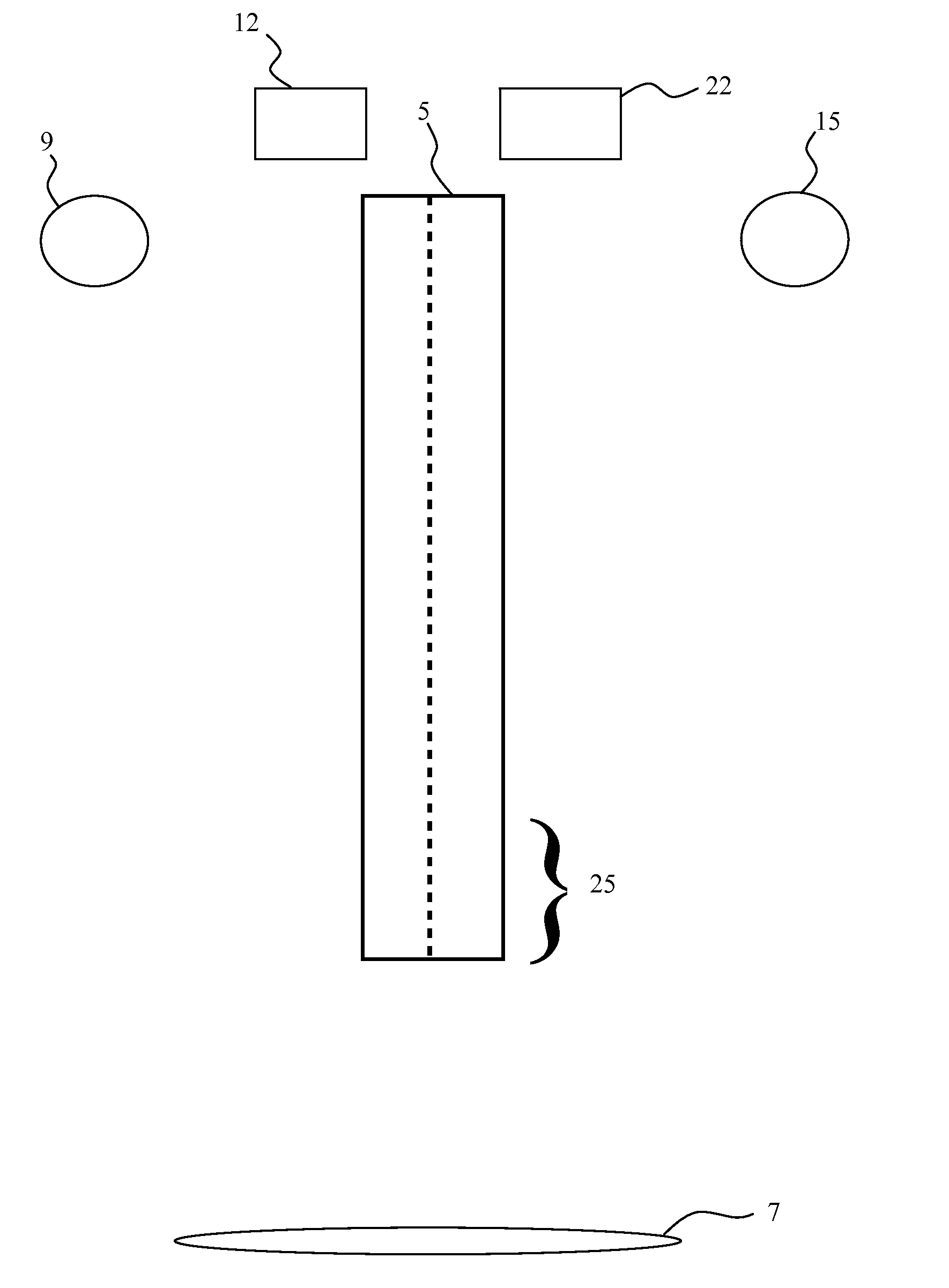
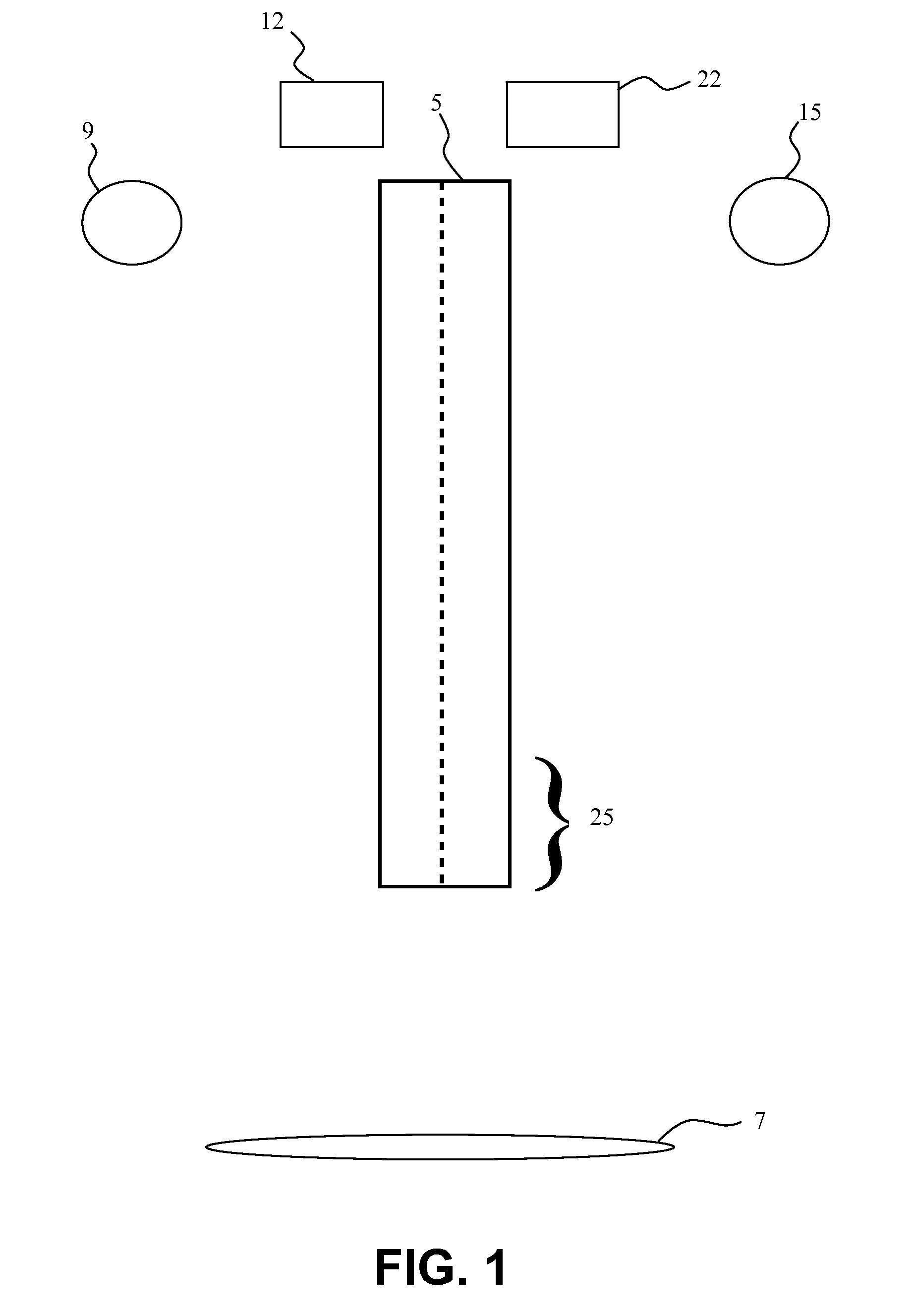
[0010]Reference will now be made to certain embodiments (e.g., certain described and / or incorporated embodiments) of the invention, partial examples of which are illustrated in the accompanying drawings. Wherever possible, the same or similar reference numbers are used in the drawings and the description to refer to the same or like parts. It should be noted that the drawings are in simplified form and are not to precise scale. In reference to the disclosure herein, for purposes of convenience and clarity only, directional terms, such as, top, bottom, left, right, up, down, over, above, below, beneath, rear, and front, are used with respect to the accompanying drawings. Such directional terms should not be construed to limit the scope of the invention in any manner.

[0011]Although the disclosure herein refers to certain embodiments, it is to be understood that these embodiments are presented by way of example and not by way of limitation. The intent of this disclosure, while discussi...


PUM

PropertyMeasurementUnit
Wavelengthaaaaaaaaaa
Pressureaaaaaaaaaa

Abstract

A medical apparatus is constructed to have a proximal end and a distal end, with the distal end including a source of mechanical tissue disruption that is configured to treat or ablate a target surface. The source of mechanical tissue disruption includes a tissue-disrupting distal end, and the medical apparatus further includes a flavored particle output for directing flavored particles in a direction toward the tissue-disrupting distal end. Another feature of the present invention includes a medical apparatus having a proximal end and a distal end. The distal end of the medical apparatus includes a source of tissue displacement that is configured to move or displace a portion of the target surface, and that is formed to have a tissue-displacing distal end. The medical apparatus can be configured to have a flavored particle output for directing flavored particles in a direction toward the tissue-displacing distal end.

Description

CROSS-REFERENCE TO RELATED APPLICATIONS[0001]This application is a continuation of U.S. application Ser. No. 12 / 336,528 (Att. Docket BI9002CNCPCNCIP), filed Dec. 16, 2008, which claims the benefit of U.S. Provisional Application No. 61 / 014,047 (Att. Docket BI9002CNCPCNCIPPR), filed Dec. 16, 2007, and which is a continuation-in-part of U.S. application Ser. No. 11 / 711,945 (Att. Docket BI9002CNCPCN2), filed Feb. 27, 2007, which is a continuation of U.S. application Ser. No. 10 / 435,325 (Att. Docket BI9002CNCPCNDIV), filed May 9, 2003, issued as U.S. Pat. No. 7,320,594, the entire contents of all which are hereby incorporated by reference. U.S. application Ser. No. 10 / 435,325 is a divisional of U.S. application Ser. No. 09 / 997,550 (Att. Docket BI9002CNCPCN), filed Nov. 27, 2001, issued as U.S. Pat. No. 6,561,803, which is a continuation of U.S. application Ser. No. 09 / 256,697 (Att. Docket BI9002CONCIP), filed Feb. 24, 1999, issued as U.S. Pat. No. 6,350,123, which is a continuation-in-p...

Claims


Application Information

Patent Timeline
IPC IPC(8): A61B17/32A61B17/3203
CPCA61B17/1644B23K26/1417A61B18/201A61B18/26A61B2018/00011A61B2018/00017A61B2018/00029A61B2018/1807A61B2217/007A61B2218/005A61B2218/008A61C1/0007A61C1/0046A61C1/0061A61C3/02A61C17/0217A61C19/06A61F2002/30092A61F2210/0014A61M3/0279A61N2005/0644B23K26/1411A61B18/20B23K26/144B23K26/146
Inventor RIZOIU, IOANA M.PIGNATELLI, FEDERICO
Owner BIOLASE TECH INC
Why Eureka
Try Eureka