
Methods and instruments for interbody fusion

a technology of interbody fusion and instruments, which is applied in the direction of prosthesis, osteosynthesis devices, surgical forceps, etc., can solve the problems of affecting the inability to perform fusion, and the inability to maintain the stability of the segment, so as to prevent the effect of retrograd

Inactive Publication Date: 2010-05-20
WARSAW ORTHOPEDIC INC
View PDF100 Cites 44 Cited by
  • Summary
  • Abstract
  • Description
  • Claims
  • Application Information

AI Technical Summary

Benefits of technology

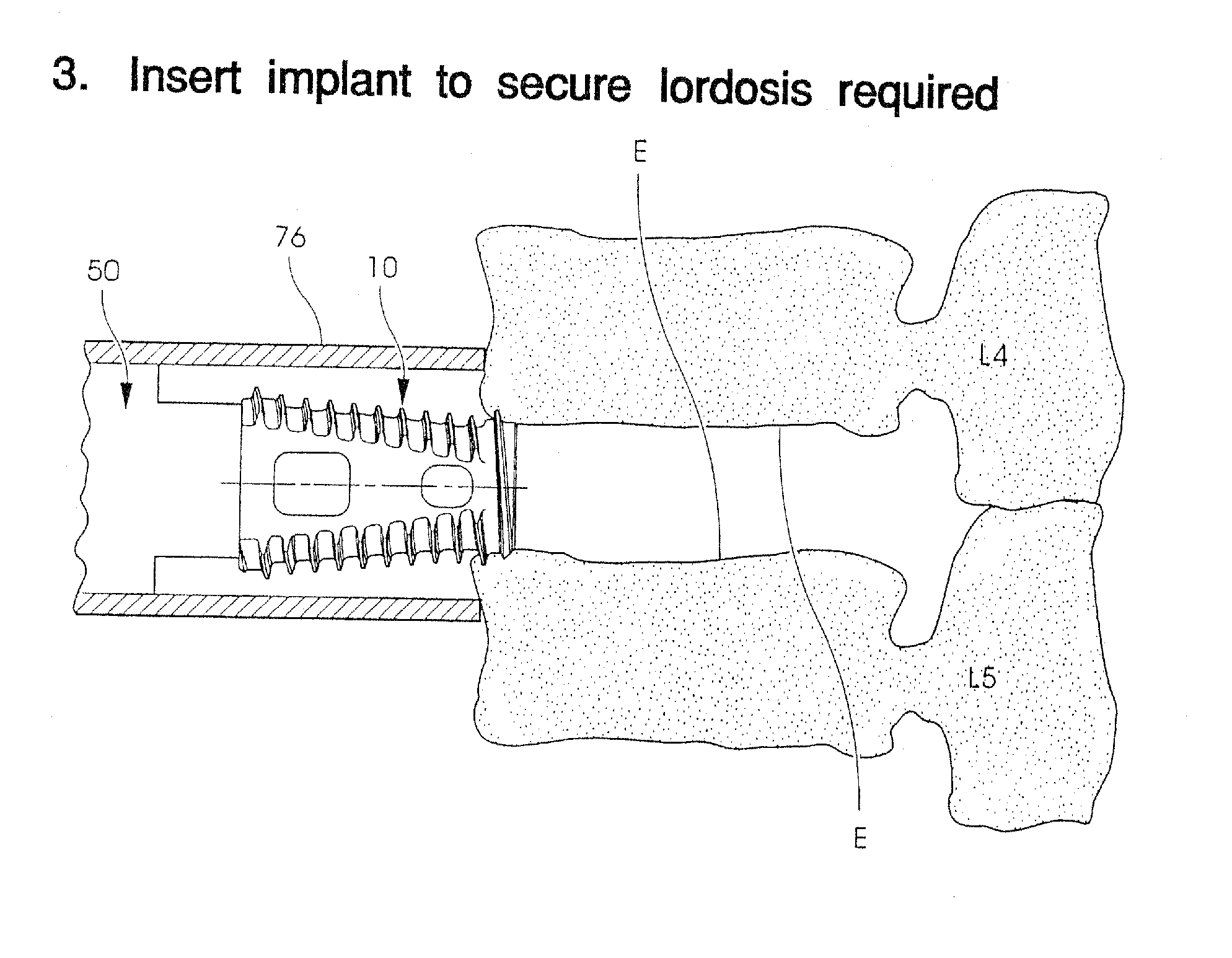
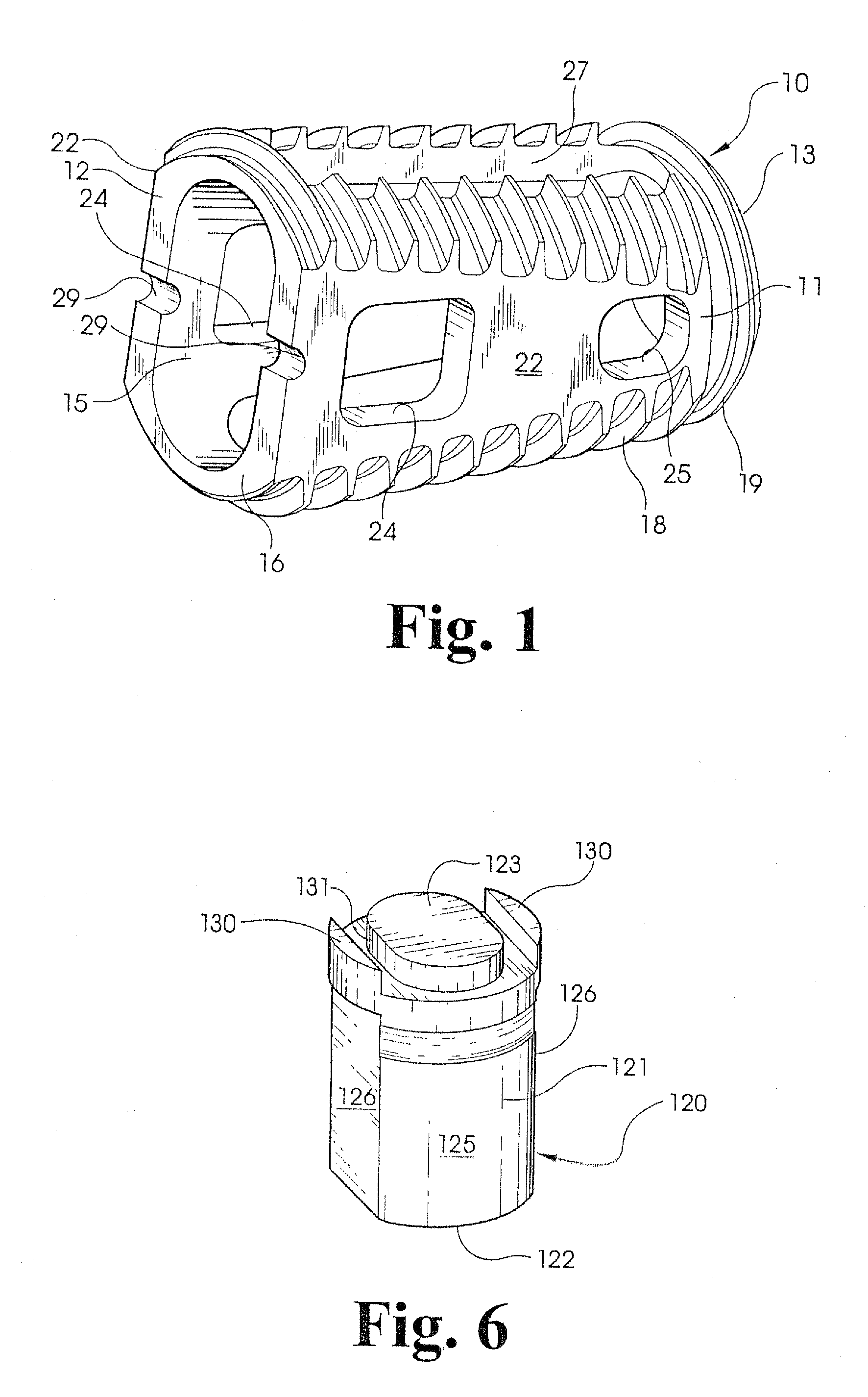
[0012]In accordance with one aspect of the invention, a novel fusion device is provided that integrates a pair of bone screws. The fusion device can be a hollow substantially cylindrical body, such as the device shown in FIG. 1. In this aspect, the device includes a pair of screw bores formed in an end face of the body. The bores are arranged so that bone screws extending through the bores will be driven into the endplates of the adjacent vertebrae. In certain features, the heads of the bone screws are recessed within the body and held in place by a common locking screw. The screws help prevent retrograde expulsion or rotation of the fusion device, or a spacer, from the disc space.

Problems solved by technology

Since the damaged disc material has been removed, something must be positioned within the intradiscal space, otherwise the space may collapse resulting in damage to the nerves extending along the spinal column.
Once fusion occurred the hardware used to maintain the stability of the segment became superfluous.
Moreover, the surgical procedures necessary to implant a rod or plate to stabilize the level during fusion were frequently lengthy and involved.

Method used


Image

  • Methods and instruments for interbody fusion
  • Methods and instruments for interbody fusion
  • Methods and instruments for interbody fusion

Examples


Embodiment Construction

[0064]For the purposes of promoting an understanding of the principles of the invention, reference will now be made to the embodiments illustrated in the drawings and specific language will be used to describe the same. It will nevertheless be understood that no limitation of the scope of the invention is thereby intended, such alterations and further modifications in the illustrated device, and such further applications of the principles of the invention as illustrated therein being contemplated as would normally occur to one skilled in the art to which the invention relates.

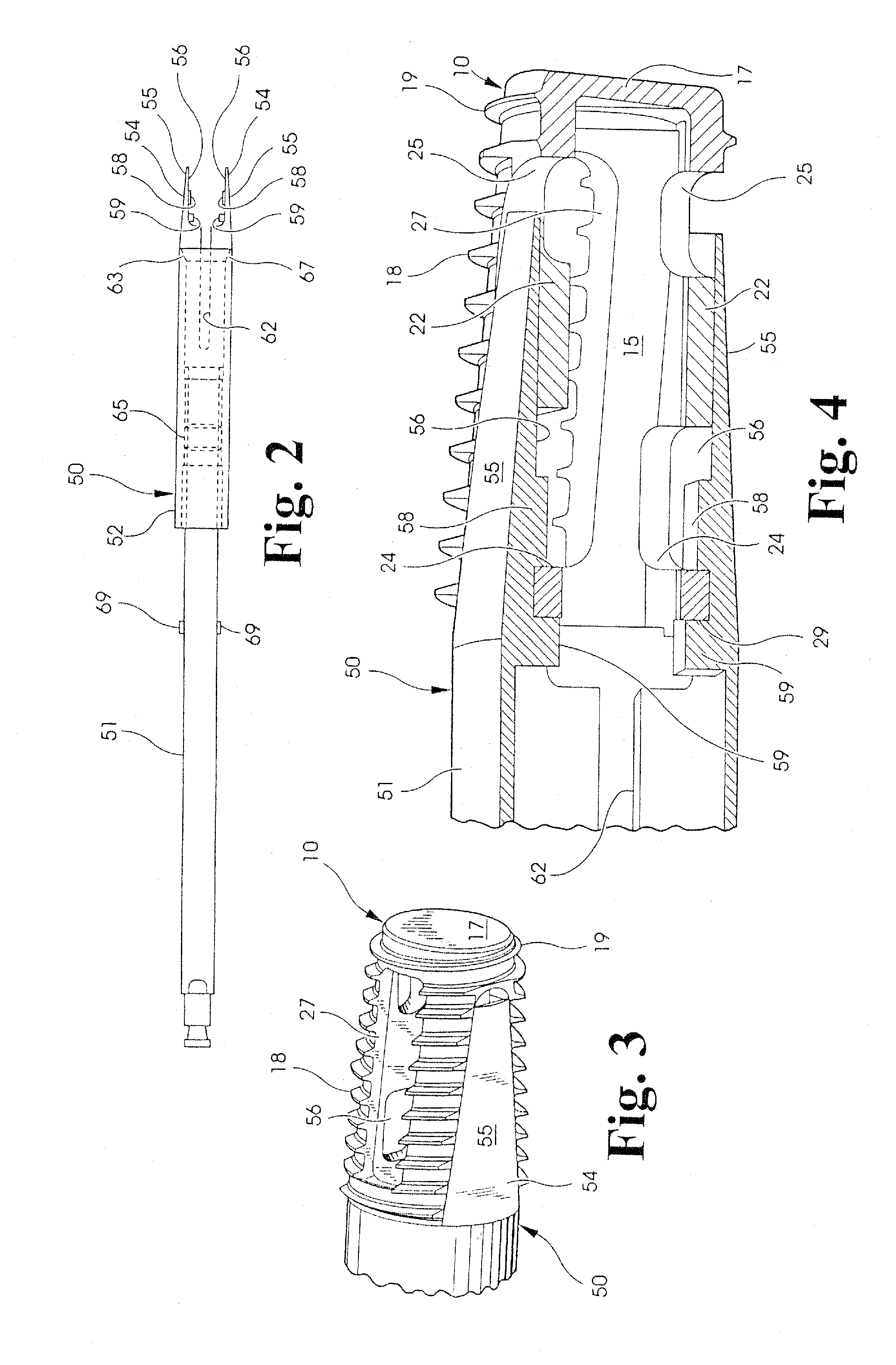
[0065]As described above, one interbody fusion device, as shown in FIG. 1, can be implanted within the intradiscal space. This interbody fusion device 10 can be implanted using the implant driver 50 shown in FIG. 2. The implant driver 50 is comprised of a shaft 51 and sleeve 52 concentrically disposed about the shaft. Tongs 54 are formed at one end of the shaft for gripping the interbody fusion device 10 for im...


PUM


Abstract

A laparoscopic surgical technique is provided for preparing a site for implantation of a novel fusion device or implant. In accordance with one embodiment of the technique, a laparoscope is provided having an outer sleeve with distraction fingers at one end to distract the disc space. The laparoscope provides a sealed working channel to the disc space, through which the disc space is distracted, the vertebral endplates and surrounding disc is reamed, and the fusion device inserted. A distraction plug is provided for centering the outer sleeve and for providing midline distraction of the disc space. In one embodiment, a fusion device includes diverging bone screws passing through an end wall and upper and lower walls of the device to engage the adjacent vertebrae. In another embodiment, a connector plate is engaged to bilaterally position fusion devices to prevent rotation and resist expulsion of the devices from the disc space.

Description

[0001]This application is a continuation-in-part of application Ser. No. 08 / 604,874, filed on Feb. 22, 1996, which is a continuation-in-part of application Ser. No. 08 / 411,017, filed on Mar. 27, 1995, all owned by the assignee of the present application.BACKGROUND OF THE INVENTION[0002]The present invention relates to methods and instruments for performing an interbody fusion of a disc space between two adjacent vertebrae. Specifically, the invention concerns laparoscopic techniques and instruments to prepare a fusion site and to insert fusion devices and implants.[0003]The number of spinal surgeries to correct the causes of low back pain has steadily increased over the last several years. Most often, low back pain originates from damage or defects in the spinal disc between adjacent vertebrae. The disc can be herniated or can be suffering from a variety of degenerative conditions, so that in either case the anatomical function of the spinal disc is disrupted. The most prevalent sur...

Claims


Application Information

Patent Timeline
Patent Type & Authority Applications(United States)
IPC IPC(8): A61F2/44A61B17/56A61B17/58A61B1/00A61B1/313A61B17/00A61B17/02A61B17/16A61B17/17A61B17/28A61B17/34A61B17/70A61B17/86A61B17/88A61B19/00A61F2/00A61F2/28A61F2/30A61F2/46
CPCA61B1/3132A61F2230/0067A61B17/025A61B17/1671A61B17/1757A61B17/282A61B17/7059A61B17/86A61B2017/00238A61B2017/00261A61B2017/0256A61B2017/3488A61B2019/5404A61B2019/5437A61F2/442A61F2/446A61F2/4601A61F2/4611A61F2002/2835A61F2002/2839A61F2002/30123A61F2002/30153A61F2002/30179A61F2002/3021A61F2002/30217A61F2002/30329A61F2002/30433A61F2002/30507A61F2002/30604A61F2002/30774A61F2002/30777A61F2002/30785A61F2002/30787A61F2002/30789A61F2002/3082A61F2002/30858A61F2002/30863A61F2002/30871A61F2002/30874A61F2002/4475A61F2002/448A61F2002/4627A61F2002/4635A61F2220/0025A61F2220/0041A61F2230/0006A61F2230/0019A61F2230/0058A61B1/3135A61B2090/3904A61B2090/3937A61F2002/30873A61F2002/30593
Inventor ZDEBLICK, THOMASMCGAHAN, THOMAS
Owner WARSAW ORTHOPEDIC INC
Learn More