
Wiper blade with electromagnetic command

a technology of electromagnetic command and wiper blade, which is applied in the field of windshield wipers for aircraft, can solve the problems of reducing the effectiveness of the seal, reducing the visibility of the pilot, and reducing the contact force of the wiper blade. achieve the effect of greater contact for

Active Publication Date: 2010-05-27
AIRBUS OPERATIONS (SAS)
View PDF28 Cites 13 Cited by
  • Summary
  • Abstract
  • Description
  • Claims
  • Application Information

AI Technical Summary

Benefits of technology

[0017]A second aspect of the disclosed embodiments minimizes wear on the windshield wiper blade element in its storage position.
[0036]It will be appreciated that this presence of passive electromagnets makes it possible to measure a current flowing through the associated coils, the current being generated by each movement of the flexible rod with respect to the rigid rod. As a result, by integrating these measurements, it is possible to calculate the distance between these rods at each moment.

Problems solved by technology

In rainy weather, water flowing over the front window or windows, and insect impacts, may reduce visibility for pilots particularly during take offs, landings and taxiing.
Elements of low rigidity, such as the seal, may be situated in the zone swept by the blade element of the windshield wiper during normal wiping (the wiping zone overlapping the seal in order to wipe a maximum zone of the window) or during its transition from the wiping zone to this storage position or vice versa, and may therefore be damaged as the blade element repeatedly passes over it.
The consequence of this is both damage to the seal and therefore reduction in its effectiveness, and aerodynamic drag that also carries with it the possibility of damage to the transparencies.
Windshield wipers comprising rigid blade elements, suited to planar surfaces, are no longer suitable for these curved shapes because contact between the windshield and the blade element is no longer achieved over the entire surface of the wiper blade during the complete wipe.
However, there is a risk that contact between the blade element and the windshield will be interrupted momentarily, either fully or in part, at high aircraft speeds, because of the air flow.
In addition, this type of windshield wiper provides no solution to the problem of potential damage to the seal or seals and to the front glass during wiping or transitions to or from the windshield wiper storage position.
What is more, if the transition involves a lifting of the arm (FIG. 1c) before it is stored, the operation of the whiffletree leads, during lifting, to the two ends of the blade element remaining in contact with the windshield, and this is likely to cause local damage to this windshield or damage to the blade element itself.

Method used


Image

  • Wiper blade with electromagnetic command
  • Wiper blade with electromagnetic command
  • Wiper blade with electromagnetic command

Examples


Embodiment Construction

[0060]The disclosed embodiments take its place in the front part of an airplane fuselage, at cockpit windshield level.

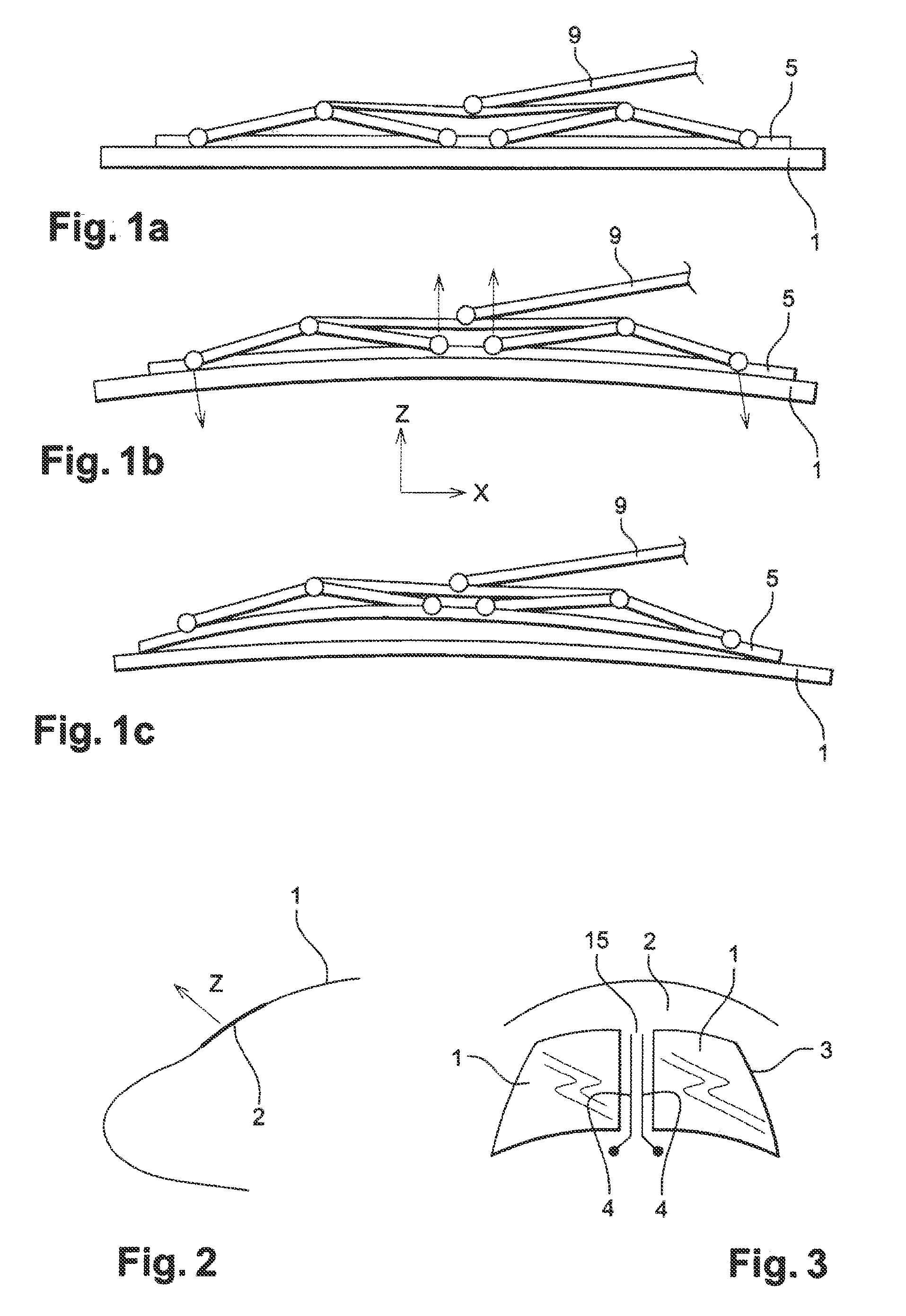
[0061]For the remainder of the description there is defined an axis known as the horizontal axis Y, tangential to the windshield locally and situated in an airplane horizontal plane. Likewise, there is defined an axis known as the interior-exterior axis Z that coincides with the local normal at a point Pi to the windshield of the airplane. Finally, an axis known as the longitudinal axis X, tangential to the windshield locally and perpendicular to the other two axes completes this frame of reference. The terms top and bottom will be employed with reference to the interior-exterior axis Z.

[0062]As may be seen from FIG. 3, the windshield in this entirely nonlimiting example has two front windows 1 connected to the fuselage 2 by a flange and a seal 3. In the example illustrated in FIG. 2, the two front windows 1 are separated by a vertical pillar 15.

[0063]A windshield wi...


PUM


Abstract

The wiper blade for a surface of the type with a dual curvature, the wiper blade including a flexible blade element and a means of applying a pressing force to at least one point of the blade element in a direction Z mostly normal to the surface, also including means of varying the pressing force over time, at least some of the points, between pre-chosen positive and negative limit values, and means of commanding the pressing force. These means for bringing about local pressure or lift are electromagnetic.

Description

BACKGROUND[0001]1. Field[0002]The disclosed embodiments lie within the field of windshield wipers and relates more specifically to windshield wipers for aircraft.[0003]2. Brief Description of Related Developments[0004]In the aeronautical field, in order to allow the pilot to see the external surroundings of the airplane, the cockpit is fitted with various windows and, in particular, with one or more front windows forming the windshield. These front windows, of which there are generally two in commercial airplanes, have hitherto conventionally been planar in shape, and their aerodynamic continuity with the fuselage at their periphery is provided by a seal.[0005]In rainy weather, water flowing over the front window or windows, and insect impacts, may reduce visibility for pilots particularly during take offs, landings and taxiing. Hence, windshield wipers are fitted on the outside of these front windows. The way these work by cyclically sweeping an arc of a disk across the window usin...

Claims


Application Information

Patent Timeline
IPC IPC(8): B60S1/04
CPCB60S1/0455B60S1/08B60S2001/3812B60S1/38B60S1/3411
Inventor LIEVEN, PATRICK
Owner AIRBUS OPERATIONS (SAS)
Learn More