Screw elevator

a screw elevator and elevator technology, applied in the direction of building lifts, transportation and packaging, etc., can solve the problems of affecting the smooth movement of the elevator, the need for extra space for screw installation, and the possibility of deformation, so as to achieve the effect of smooth upward/downward movement of the elevator and overall elevator durability

Inactive Publication Date: 2010-05-27
HIWIN TECH
View PDF5 Cites 20 Cited by
  • Summary
  • Abstract
  • Description
  • Claims
  • Application Information

AI Technical Summary

Benefits of technology

[0007]The primary objective of the present invention is to provide a screw elevator, which employs a power unit to drive the car to move upwards and downwards, wherein the cable is combined at the center of the top of the car, which is just the center of gravity of the car, so that although the principle of screw is applied, the car is subjected to a relatively small torque and shares the pulling fore and weight evenly, thus making the overall elevator more durable and the upward / downward movement of the elevator relatively smooth.
[0008]The secondary objective of the present invention is to provide a screw elevator in which the screw is installed within the space of the counterweight guide rails without providing extra installation space, thus making the overall structure layout and design relatively simple and reduce the design and construction cost.
[0009]The third objective of the present invention is to provide a screw elevator in which the length of the screw is just half of the total travel of the car, so that the production of the screw elevator of the present invention is more simplified, and the travel of the screw elevator of the present invention is relatively long, thus widening the application range.
[0010]The fourth objective of the present invention is to provide a screw elevator in which the power unit includes a motor which is interiorly provided with a motor rotor in which is provided a driving nut to be screwed on the screw, so that the screw elevator of the present invention doesn't require a complicated deceleration mechanism, thus having the advantages such as lower cost of parts, occupying less space, simple design and easy to install.

Problems solved by technology

Furthermore, due to the limitation of the guide shoes installed on the elevator car, the elevator car will linearly move upwards and downwards along the screw.
As a result, the car is likely to deform due to the torque, thus affecting the smoothness of the movement of the elevator.
In addition, not only does the space of movement of elevator provide the space for the arrangement of the guide rails, but also extra space is needed for installing the screw.
Therefore, the difficulty of design and the cost are correspondingly increased.
Hence, it is found that the screw is too long, thus increasing the difficulty of production.
Additionally, since the power unit must employ the deceleration mechanism to obtain the relatively large torque and proper rotating speed to drive the nut, the use and arrangement of the deceleration mechanism not only increases the cost but occupy the space of movement of the elevator.

Method used


Image

  • Screw elevator
  • Screw elevator
  • Screw elevator

Examples


Embodiment Construction

[0019]The present invention will be clearer from the following description when viewed together with the accompanying drawings, which show, for purpose of illustrations only, the preferred embodiment in accordance with the present invention.

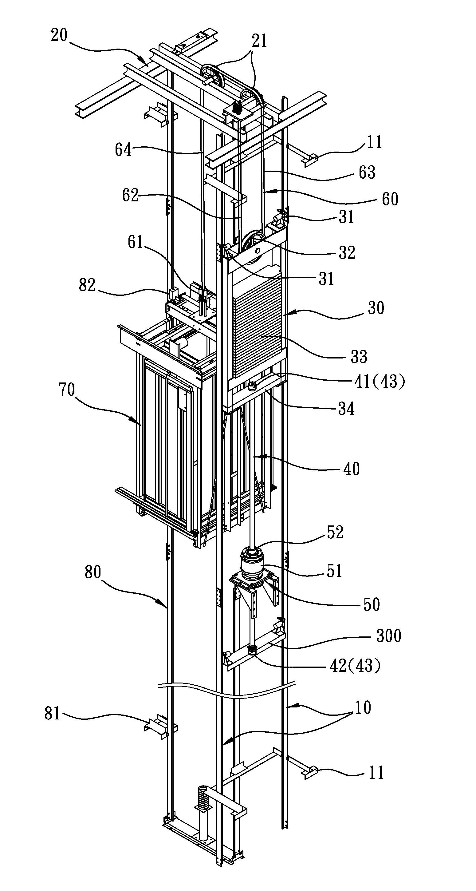
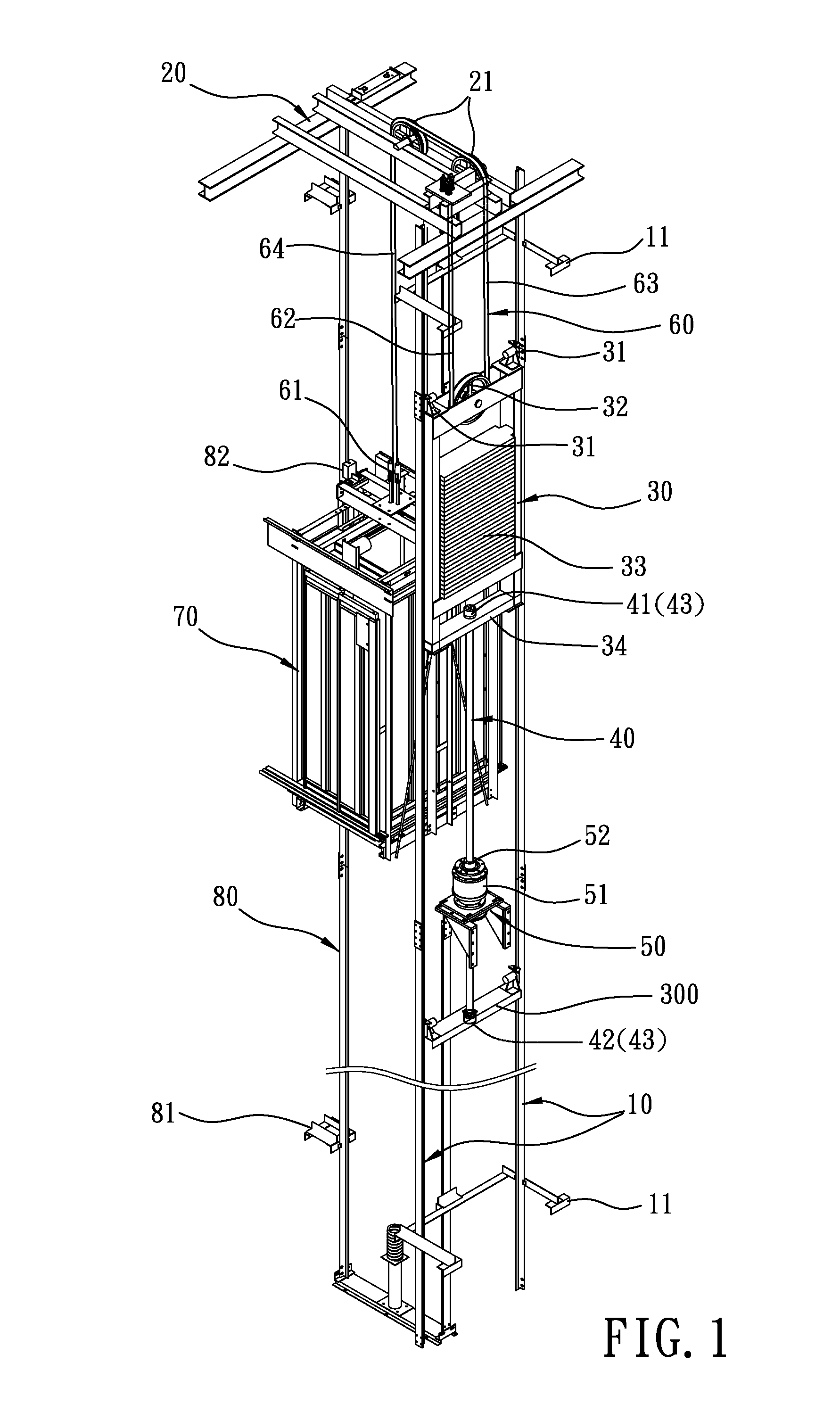
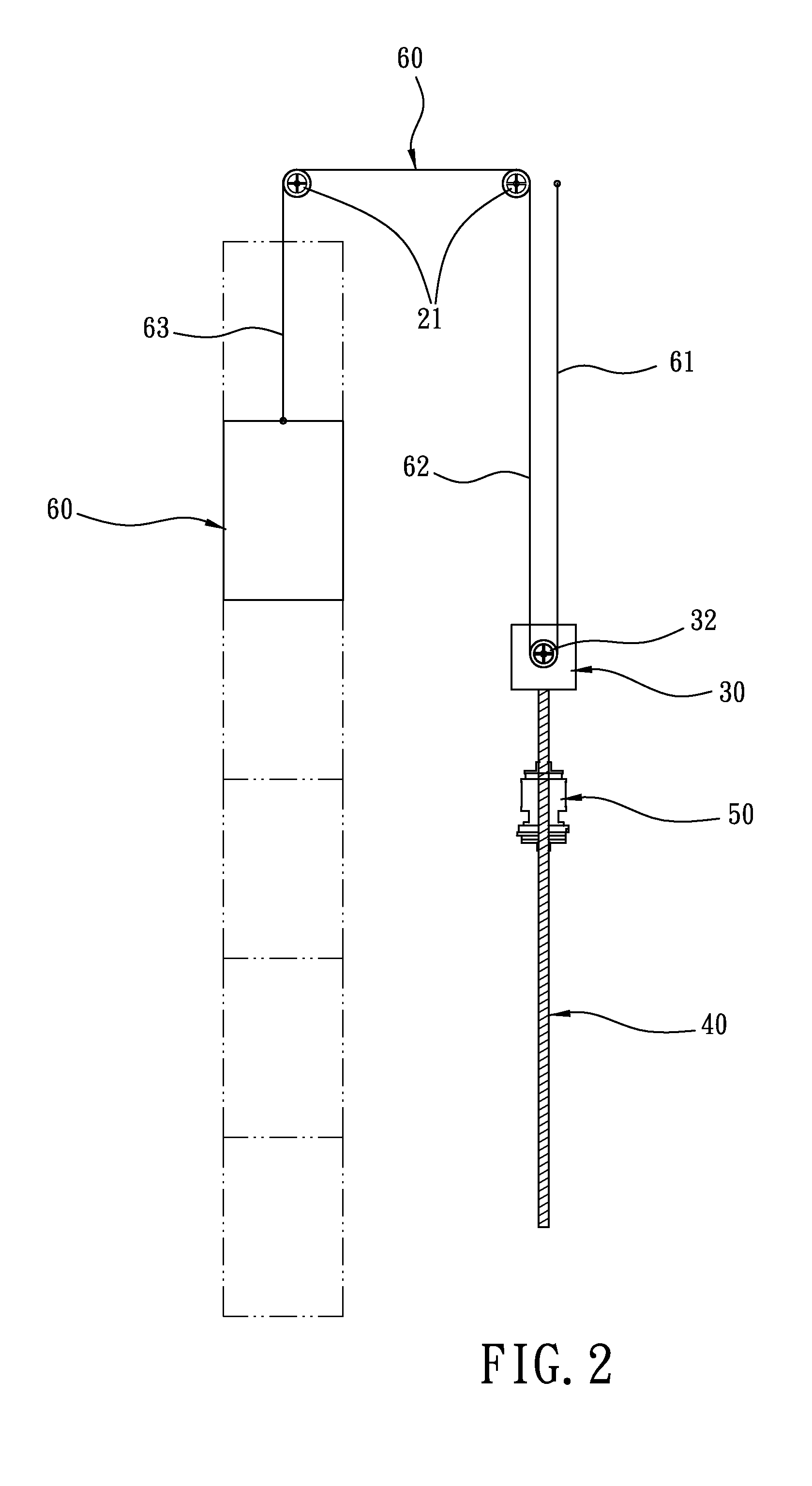
[0020]A screw elevator in accordance with a preferred embodiment of the present invention comprises a pair of counterweight guide rails 10, a beam frame 20, a counterweight frame 30, a screw 40, a power unit 50, a cable 60, a car 70 and a car guide rail 80.

[0021]The pair of counterweight guide rails 10 is disposed on a fixed wall surface by at least one guide rail bracket 11.

[0022]The beam frame 20 is an H-shaped structure made of angle steel. The beam frame 20 is disposed above and connected to the counterweight guide rails 10. The beam frame 20 is provided with a pair of deflection wheels 21.

[0023]The counterweight frame 30 is located between the pair of counterweight rails 10 by two guide shoes 31. The counterweight frame 30 is provided at the...


PUM


Abstract

A screw elevator comprises a pair of counterweight guide rails, a pair of deflection wheels, a counterweight frame, a screw, a power unit, a cable, a car and a car guide rail. The power unit, the screw and the counterweight frame are all disposed between the pair of counterweight guide rails. The power unit drives the screw and the counterweight frame to move, and then the movement of the screw will drive the cable to make the car move upwards and downwards along the car guide rail. The cable has one end fixed at a position above the counterweight rails and the other end of the cable is finally fixed at the center of the top of the car after being wound around a traction wheel and straddled over the deflection wheels.

Description

BACKGROUND OF THE INVENTION[0001]1. Field of the Invention[0002]The present invention relates to a screw elevator, and more particularly to a screw elevator which is driven to move using a screw with a length that is half of the travel of the elevator.[0003]2. Description of the Prior Art[0004]A conventional screw elevator, as disclosed in Taiwan Patent No. 1296606, entitled “two-way screw drive mechanism for an elevator”, is provided with a screw and a power unit that are both placed at one side of an elevator car. The power unit includes a motor and a deceleration mechanism and is directly connected with the elevator car. The nut is installed in the deceleration mechanism, and the screw is fixed on the beam structure above the elevator car. When being actuated, the motor will output power to the nut through the deceleration mechanism, so that the nut will move along the screw to drive the elevator car to move synchronously. Furthermore, due to the limitation of the guide shoes ins...

Claims


Application Information

Patent Timeline
Patent Type & Authority Applications(United States)
IPC IPC(8): B66B11/08
CPCB66B9/025
Inventor LIAO, TIEN-TZUHUANG, CHUN-WEI
Owner HIWIN TECH
Why Eureka
Try Eureka