
Waste treatment vessel featuring tilt mechanism and associated door arrangement

Inactive Publication Date: 2010-05-27
ESTECH
View PDF7 Cites 8 Cited by
  • Summary
  • Abstract
  • Description
  • Claims
  • Application Information

AI Technical Summary

Benefits of technology

[0013]One of the key aspects of the present invention is the use of a system that separates the doors from the vessel in such a way that the vessel is opened widely to allow the waste mass to be more readily and conveniently loaded and unloaded in the processing cycle, so as to “debottleneck” the waste compression / loading process.
[0014]This present invention provides improvements in the functionality of waste autoclave systems by increasing loading and unloading efficiency and the resultant overall throughput efficiency.
[0029]It is preferred that the autoclave preferably is disposed at an angle to the horizontal for loading so as to assist in the loading of the uncompressed waste mass or bales, and it is also preferred that the autoclave is rotated during loading so as to assist in the loading of the loose waste mass or compressed bales.
[0031]The conveyor additionally preferably comprises a conveyor belt and a mechanical forcing arrangement for rapidly and positively charging the bales into the autoclave. The autoclave most preferably is disposed at an angle to the horizontal so as to assist in the loading of the bales, and is rotated during loading so as to assist in the loading of the bales. It is preferred that the conveyor, or at least its loading terminal segment, is linear and faces directly into the autoclave in order to the speed loading.
[0032]In a preferred embodiment, the conveyor has a loading end and a discharge end, and there is a barrier disposed between the conveyor loading end and the conveyor discharge end, such that the conveyor extends through the barrier. The barrier may be part of an entire chamber holding the autoclave so as to better separate and maintain the area of the autoclave as a clean area.
[0039]The facility and process preferably allows for the waste to be compression baled on the tipping floor, thereby allowing the entire vessel area to be a clean zone, if desired. In a preferred embodiment, there may be provided a barrier between the tipping floor area and the autoclave, with the conveyor extending from the tipping floor through the barrier to the autoclave, in order to better isolate the autoclave area as a clean area.

Problems solved by technology

Systems to date have not solved the core problem, which is to rapidly load an autoclave, preferably while rotating, with a designed or predetermined load of material.

Method used


Image

  • Waste treatment vessel featuring tilt mechanism and associated door arrangement
  • Waste treatment vessel featuring tilt mechanism and associated door arrangement
  • Waste treatment vessel featuring tilt mechanism and associated door arrangement

Examples


Embodiment Construction

[0052]In accordance with the foregoing summary, the following provides a detailed description of the preferred embodiment, which is presently considered to be the best mode thereof.

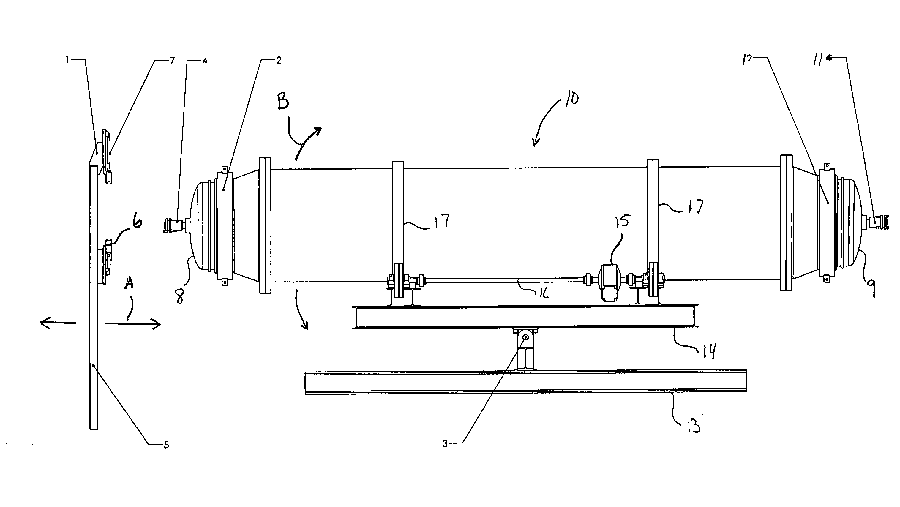
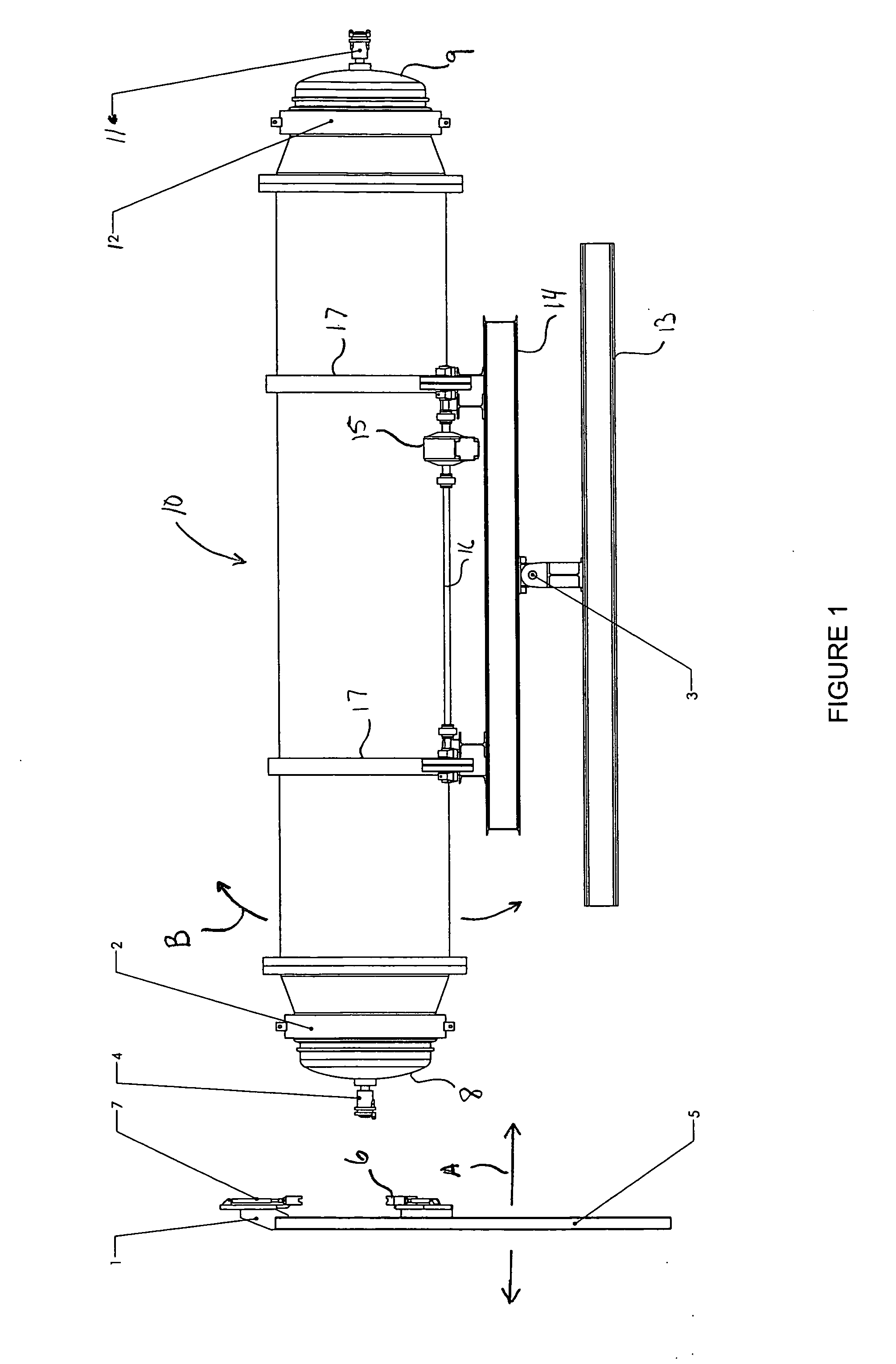
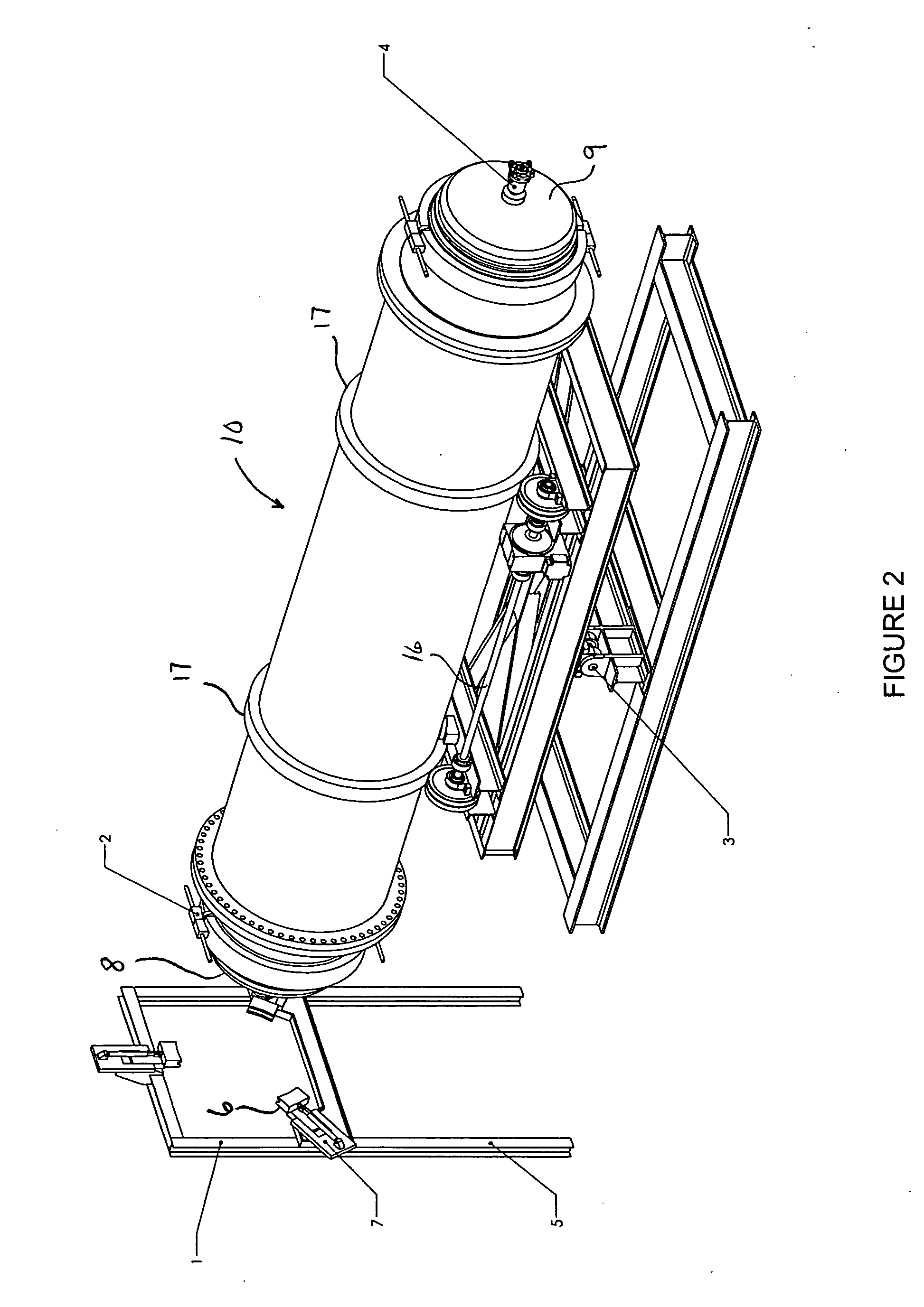
[0053]FIGS. 1-6 and 8 are views of a vessel and door system for processing solid waste products in accordance with one embodiment of the present invention. Like reference numerals are used to refer to corresponding elements and features in each of the Figures as described below.

[0054]FIG. 1 is an elevation view of a vessel and door system for processing solid waste products in accordance with one embodiment of the present invention. FIG. 1 shows a side view of the autoclave vessel 10 in normal operating position, with doors 8 and 9 attached. For simplicity, steam hoses and other details are not shown.

[0055]FIG. 1 shows door support unit 1 having door engagement clamps such as 7 that are adapted to capture and retain doors such as 8 or conversely door 9 when such an apparatus as door support unit 1 is disp...


PUM


Abstract

The present invention includes an apparatus for processing solid waste products, the apparatus comprising: (a) a rotatably mounted cylindrical vessel having a first end and a second end, at least one of the ends terminating in an opening to allow access to the interior of the vessel and to sealably close the vessel to allow pressurization thereof, the vessel adapted to move between an operating position and loading-discharge position wherein the first end is higher than the second end; (b) at least one door adapted to sealably close the vessel at at least one end, the door adapted to be completely separated from the vessel; (c) a steam inlet for injecting steam into the vessel; (d) at least one actuator for moving the vessel between an operating position and a loading-discharge position wherein the first end is higher than the second end; and each opening provided with a door that is completely detachable from the vessel; and (e) a respective attachment portion adapted to attach each door to the vessel.

Description

TECHNICAL FIELD[0001]The present invention relates to the treatment of municipal solid waste (“MSW”) and the like. This invention disclosure presents a means of utilizing steam to heat and dry wet solids inside a rotating vessel with at least one entry and exit door.BACKGROUND OF THE INVENTION[0002]A waste autoclave is a form of solid waste treatment that utilizes heat, steam and pressure of an industrial autoclave in the processing of waste. Saturated steam is pumped into the autoclave at elevated temperatures. The pressure in the vessel is maintained for a temperature-dependent period to allow the process to fully “cook” the waste. The autoclave process provides an effective pathogen and virus kill.[0003]The “cooking” process causes plastics to soften and flatten, paper and other fibrous material to disintegrate into a fibrous mass, bottles and metal objects to be cleaned, and labels etc. to be removed.[0004]Rotating waste autoclaves provide mechanical forces to further process th...

Claims


Application Information

Patent Timeline
IPC IPC(8): A61L2/07
CPCA61L11/00
Inventor MICHALEK, JAN K.THOMAS, THEODORE J.
Owner ESTECH
Learn More