Support cushion for fast inflation and deflation

a technology of support cushion and inflation, which is applied in the direction of functional valve types, sofas, transportation and packaging, etc., can solve the problems of affecting the support and protection effect, easy displacement or impact, and affecting airflow, so as to prevent air leakage, facilitate switching, and reduce the effect of affecting the stability of the soffi

Inactive Publication Date: 2010-06-03
CHAO RICHARD
View PDF26 Cites 5 Cited by
  • Summary
  • Abstract
  • Description
  • Claims
  • Application Information

AI Technical Summary

Benefits of technology

[0008]The primary object of the present invention is to overcome the foregoing shortcomings and prevent air from leaking through the air valve to cause drop of air pressure in an inflation object and result in ineffective support.
[0009]To achieve the foregoing object the present invention provides a support cushion for fast inflation and deflation which comprises an air pouch containing an orifice and an inflation chamber, and an air valve located on the air pouch. The air valve includes a valve base disposed in the orifice. The valve base has at least one air vent leading to the inflation chamber. The air valve also includes a valve cover coupling with the valve base to form an accommodating trough. The valve cover includes a connecting portion extended from the surface thereof, a through hole in the connecting portion and at least one anchor member located on a side wall of the connecting portion. The air valve further has a valve pillar located in the accommodating trough that contains an isolating portion and a tube located on the isolating portion and run through the through hole. The isolating portion has at least one first opening located on a side wall thereof and the tube has a second opening at the top end thereof communicating with the first opening. The isolating portion further has a butting surface at the bottom. The valve pillar has a first position relative to the valve base such that the butting surface is moved away from the air vent and a second position relative to the valve base such that the butting surface blocks the air vent. The tube further has a butting portion. The air valve also has a locking member coupling with the butting portion of the valve pillar. The locking member has a through hole run through by the tube and at least one track which accommodates the anchor member and has at least one elevation difference between two ends. Upon the locking member receiving a turning force the track moves a displacement relative to the anchor member to switch the valve pillar between the first position and the second position.
[0010]When the locking member is turned the valve pillar is moved up and down in the accommodating trough at the first position to allow air to flow through the air vent and the first opening, and at the second position to stop airflow through the air vent and the first opening, thus a fast switching between a flowing condition and a sealing condition can be accomplished. In the sealing condition, a retaining relationship is formed between the locking member and the valve pillar, and the butting surface tightly seals the air vent to prevent air leakage caused by inadvertent touching or excessive air pressure. Thus, the structure is simpler, air tightness is enhanced and operation is much easier.

Problems solved by technology

In an inflated condition the air valve determines the internal pressure of gas stored in the support cushion and thus affects the support and protection effect thereof.
However, during inflation the metering plug is not being gripped by any means, hence is easily displaced or impacted by external forces, and moved in the space formed between the valve base and valve.
Airflow could be hindered or inflation air pressure could be unstable.
In such a structure the valve also moves without any retaining means, structural stability is not desirable during switching of airtight and air flowing conditions.
Moreover, in the airtight condition the valve butts the value cap through merely the internal air pressure without support of a mechanical means, hence air leakage easily takes place.
Inadvertent impact also easily causes escaping of the valve and results in air leakage.
But adopted such a structure on a nursing apparatus filled with air, the internal air pressure could be excessively high under squeezing, and the valve pillar could also move under the air pressure to form a gap between the coupling portion and the round boss, and result in air leakage through the gap.
Adopted on the inflation nursing apparatus, as the nursing apparatus has a greater internal air pressure, and the surface of the inflation nursing apparatus is easily subject to squeezing and results in increasing of the internal pressure, leakage easily occurs.

Method used


Image

  • Support cushion for fast inflation and deflation
  • Support cushion for fast inflation and deflation
  • Support cushion for fast inflation and deflation

Examples


Embodiment Construction

[0018]The present invention will now be described in more detail hereinafter with reference to the accompanying drawings as follows:

[0019]To make it easier to fully understand the object of the invention, its structure, innovative features, and performance, a preferred embodiment together with the attached drawings for the detailed description of the invention is provided below. Only some embodiments of the present invention have been illustrated in the drawings, but it should be noted that many other modifications are conceivable within the scope of the following claims.

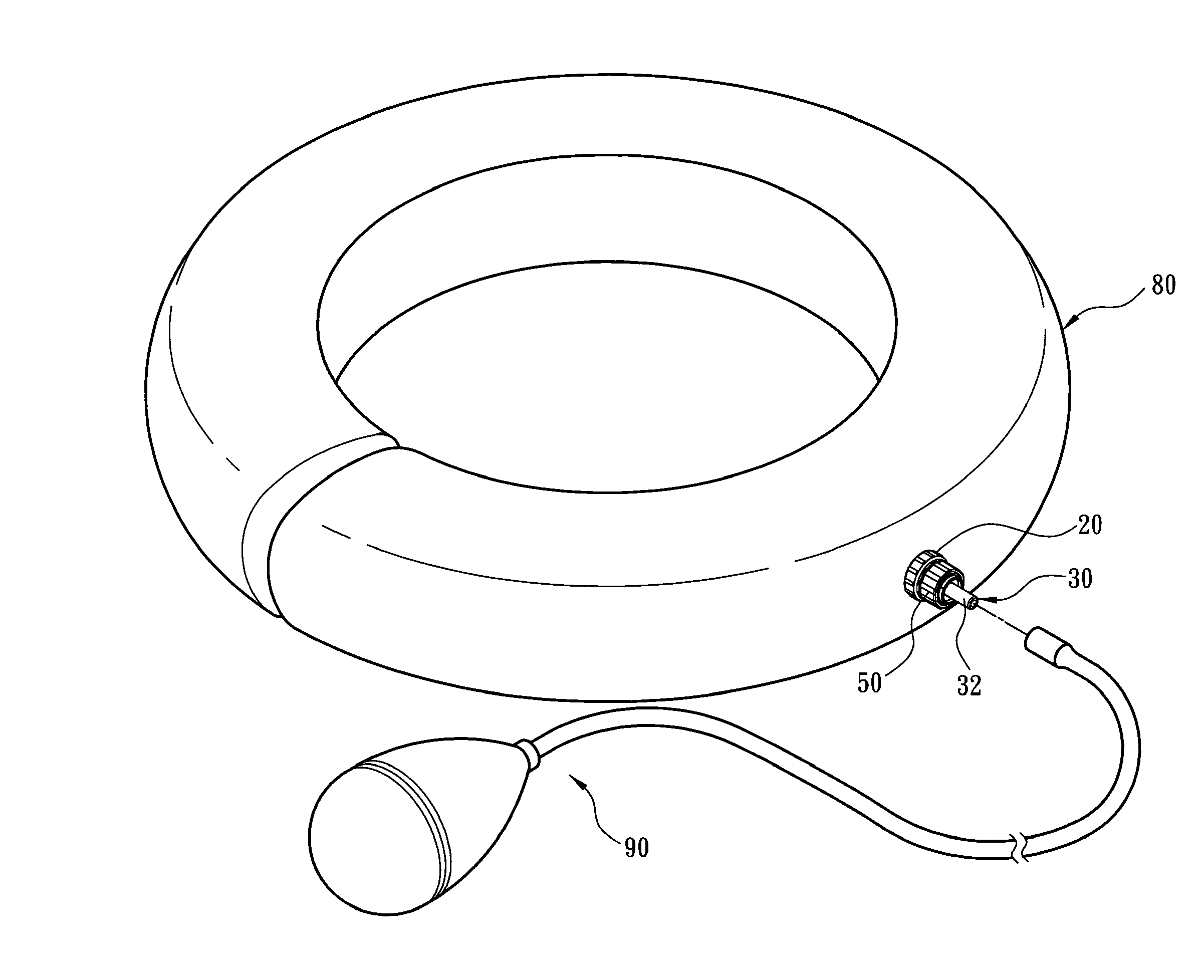
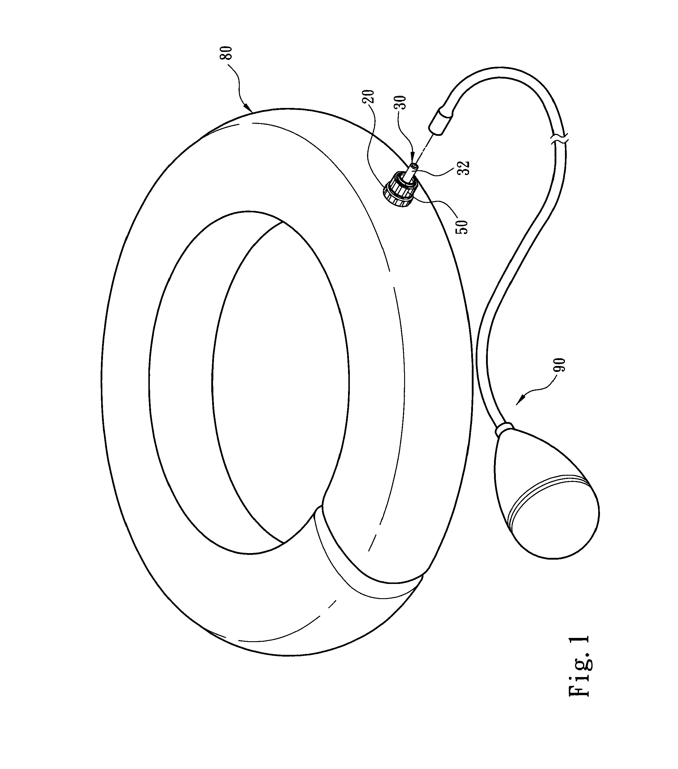
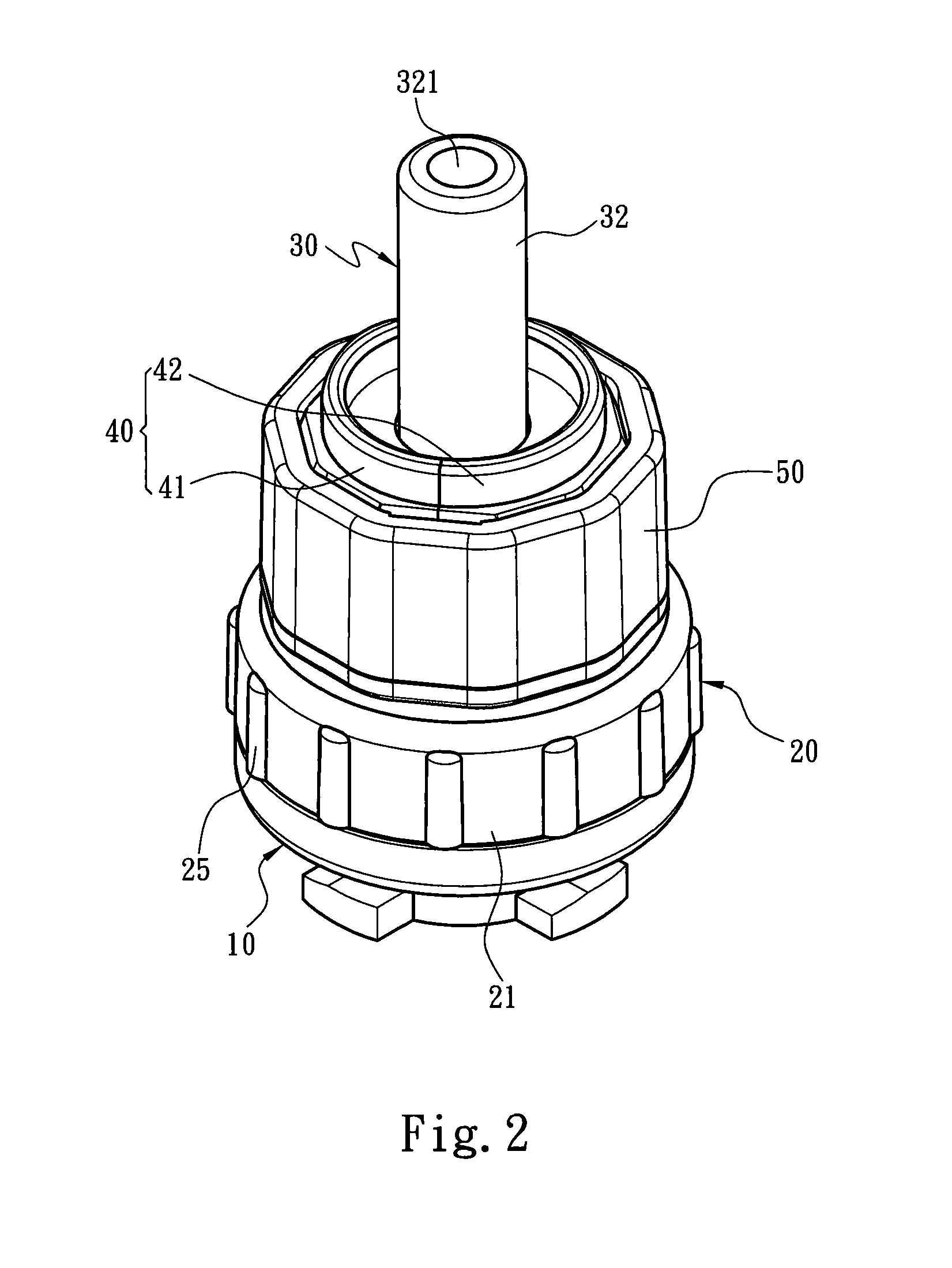
[0020]Please refer to FIGS. 1 through 4A for an embodiment of the invention. The support cushion of the present invention comprises an air pouch 80 and an air valve located on the air pouch 80. The air pouch 80 includes an orifice 81 and an inflation chamber. The air valve is connected to an inflation device 90 and includes a valve base 10 located in the orifice 81, a valve cover 20 fastened to an upper end of the v...


PUM


Abstract

A support cushion for fast inflation and deflation comprises an air pouch and an air valve located on the air pouch. The air valve includes a valve base, a valve cover, a valve pillar and a locking member. The valve base has at least one air vent leading to the air pouch. The valve cover is coupled on the valve base to form an accommodating trough to accommodate the valve pillar. The valve pillar has a first opening and a second opening communicated with each other. The valve pillar also has a first position relative to the valve base to allow air to pass and a second position to block the airflow. The locking member can receive a turning force to drive the valve pillar to switch between the first and second positions. Operation is simpler and faster switch can be achieved, and leakage of air can be avoided.

Description

[0001]This application is a continuation-in-part, and claims priority, of from U.S. patent application Ser. No. 11 / 406,250 filed on Apr. 19, 2006, entitled “AIR VALVE STRUCTURE FOR INFLATABLE ARTICLES”.FIELD OF THE INVENTION[0002]The present invention relates to a support cushion for fast inflation and deflation and particularly to an inflation support cushion that is airtight and easy to use.BACKGROUND OF THE INVENTION[0003]Inflation support cushion is widely used for medical or rehabilitation purpose, and can be put on hands, feet, waist or neck, or can be carried to support user's joints for preventing from impact. In a conventional support cushion, aside from selecting a desired outer layer material to contain gas, an air valve to inflate and deflate the gas is the most important element. In an inflated condition the air valve determines the internal pressure of gas stored in the support cushion and thus affects the support and protection effect thereof.[0004]U.S. Pat. No. 4,728...

Claims


Application Information

Patent Timeline
Patent Type & Authority Applications(United States)
IPC IPC(8): A47C16/00F16K15/20
CPCF16K15/20Y10T137/3584
Inventor CHAO, RICHARD
Owner CHAO RICHARD
Why Eureka
Try Eureka