Evaporation fuel processing system and purging method therefor

Inactive Publication Date: 2010-06-03
HONDA MOTOR CO LTD
View PDF20 Cites 18 Cited by
  • Summary
  • Abstract
  • Description
  • Claims
  • Application Information

AI Technical Summary

Benefits of technology

[0011]The present invention solves the above-noted problems, and has the object of providing an evaporation fuel processing sy

Problems solved by technology

Incidentally, there are times when after fuel has been filled into the fuel tank, running of the internal combustion engine may be stopped for long periods of time.
At such times, inside the fuel tank, a large amount of evaporation fuel is easily generated, whereas the frequency of purging of evaporation fuel from the canister becomes quite small.
As a re

Method used


Image

  • Evaporation fuel processing system and purging method therefor
  • Evaporation fuel processing system and purging method therefor
  • Evaporation fuel processing system and purging method therefor

Examples


first embodiment

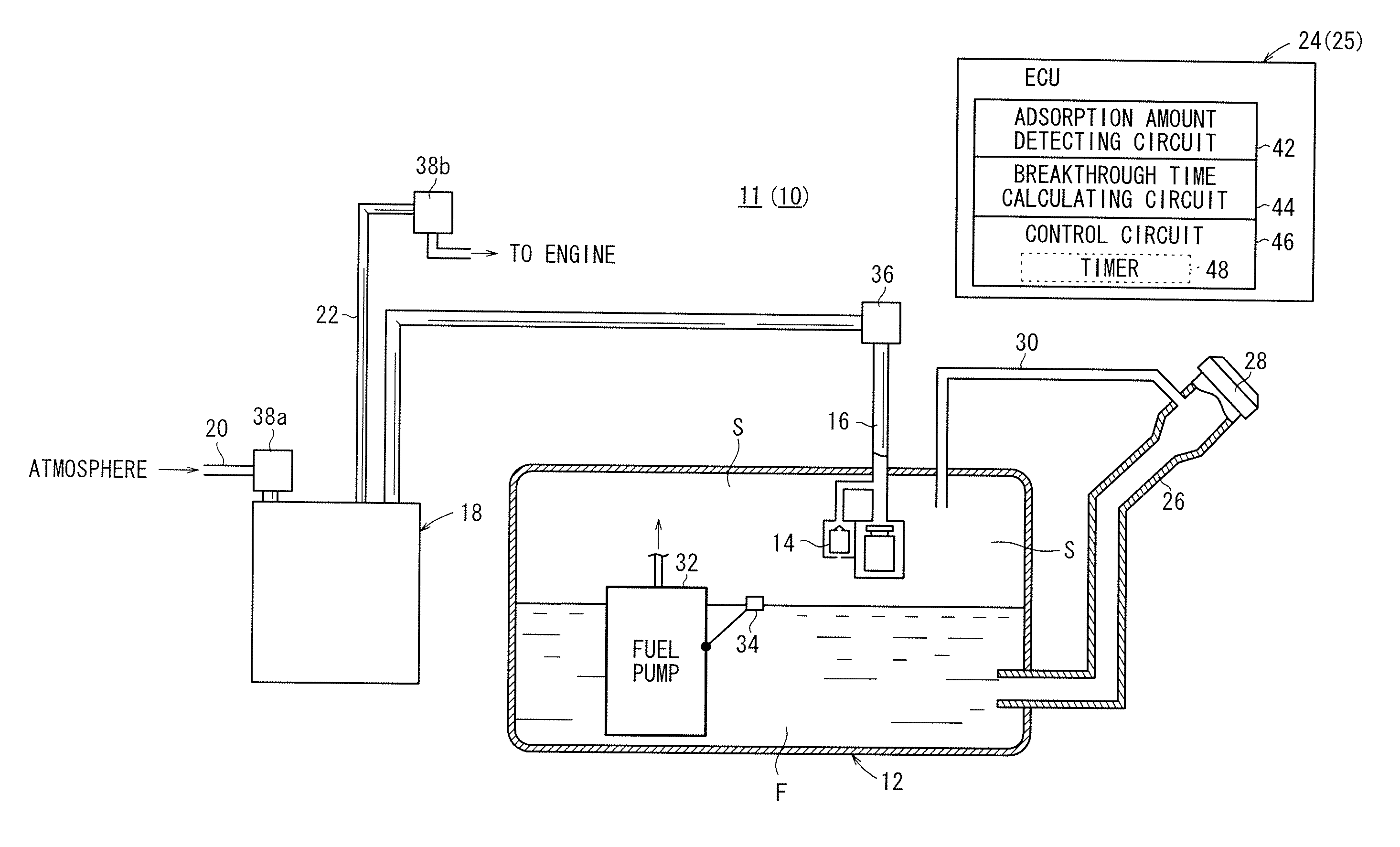
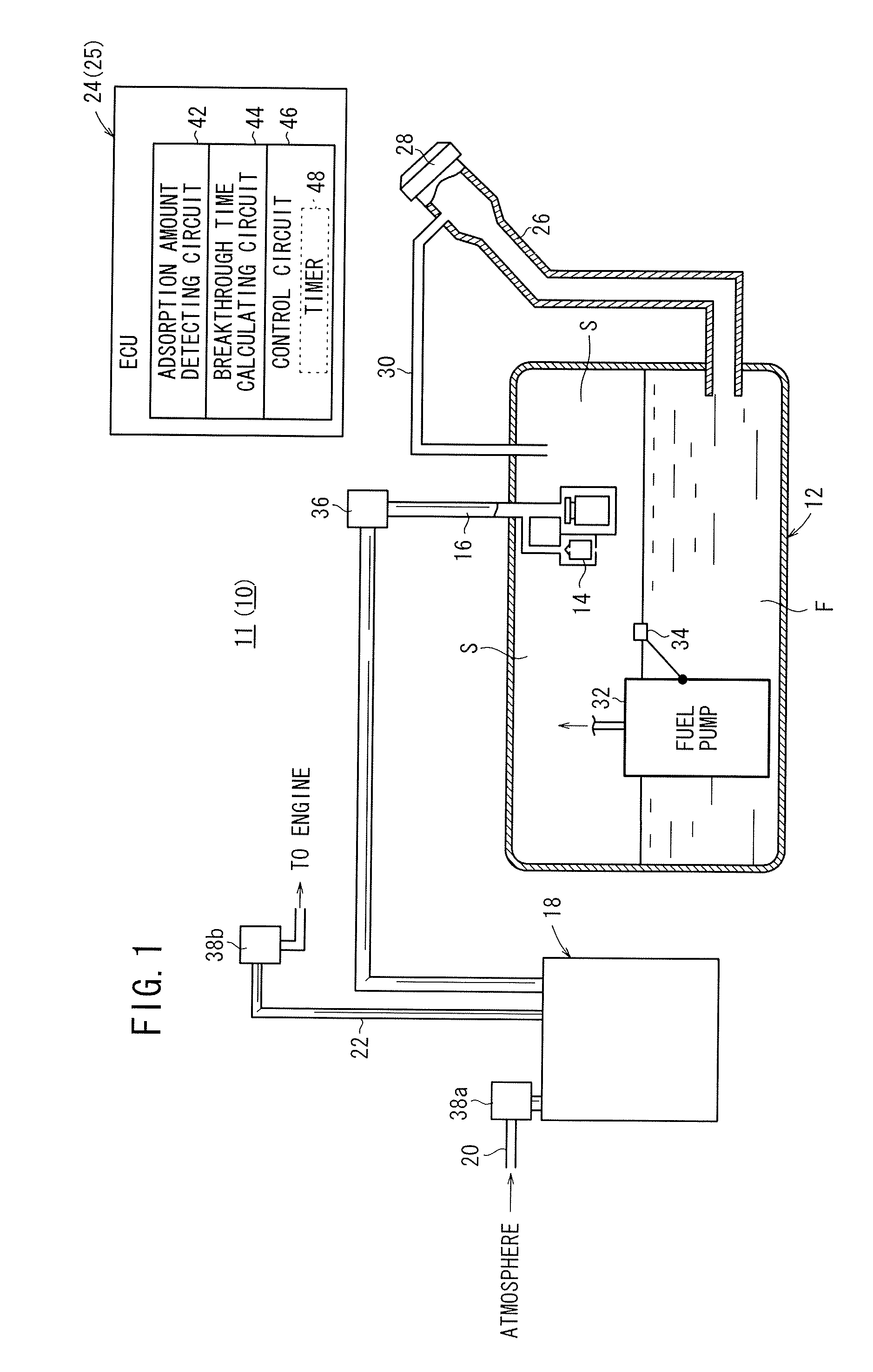
[0045]FIG. 1 is an outline schematic view of fuel tank equipment 11, to which an evaporation fuel processing system 10 according to the present invention is applied. In particular, the fuel tank equipment 11 preferably is applied to a hybrid system in which an engine (not shown) and a motor (not show) are used in tandem.

[0046]The fuel tank equipment 11 comprises a fuel tank 12 that stores a fuel F therein, a vapor passage (first communication passage) 16 through which an evaporation fuel (vapor) from inside the fuel tank 12 is introduced from a float 14, a canister 18 connected to the vapor passage 16 and which adsorbs the evaporation fuel, a drain passage 20 for communicating between the canister 18 and external air, through the drain passage 20 external air being introduced into the canister 18 when the evaporation fuel is purged, a purging passage (second communication passage) 22 through which the evaporation fuel that has been adsorbed by the canister 18 is suctioned (purged) i...

second embodiment

[0068]In this manner, before the breakthrough time of the canister 18 has elapsed, when the engine is started, variations in the adsorption amount of the canister 18, which vary in accordance with the running time of the engine, are taken into consideration, whereupon the breakthrough time of the canister 18 can be recalculated. As a result thereof, the state of the canister 18 can be detected with higher precision, and a suitable purging process can be implemented reliably.

[0069]FIG. 6 is an outline schematic view of fuel tank equipment 61, to which an evaporation fuel processing system 60 according to a third embodiment of the present invention is applied. The fuel tank equipment 61 is of a structure similar to that of the fuel tank equipment 11, and features thereof, which are the same as those of the fuel tank equipment 11, are designated by the same reference characters, and detailed descriptions of such features shall be omitted. Further, in the descriptions of the fourth emb...

third embodiment

[0073]The vapor passage 16, the canister 18, the purging passage 22, the purge control valve 38b, a temperature sensor 66 and the ECU 62 collectively constitute the evaporation fuel processing system 60 according to the The evaporation fuel processing system 60 comprises a canister adsorption capacity detecting device 70, and the canister adsorption capacity detecting device 70 comprises the adsorption amount detection circuit 64 and the breakthrough time calculating circuit 44.

[0074]Operations of the fuel tank equipment 61 shall be described along with the flowchart shown in FIG. 9, in relation to a purging method in accordance with the third embodiment of the present invention. Concerning steps thereof, which are the same as the purging method according to the first embodiment shown in FIG. 4, detailed descriptions of such steps shall be omitted.

[0075]At first, when filling of fuel into the fuel tank 12 (step S21) is carried out, because a certain amount of evaporation fuel is in...


PUM


Abstract

An evaporation fuel processing system is equipped with a vapor passage, a canister, a purging passage, a purge control valve, a filling amount detector, and an ECU. The ECU comprises an adsorption amount detecting circuit that detects the adsorption amount of an evaporation fuel, which is adsorbed by the canister upon filling of the fuel at a time when a fuel is filled into a fuel tank, a breakthrough time calculating circuit that calculates a time, based on the detected adsorption amount, at which the canister would experience breakthrough in the event that the evaporation fuel were not purged into an engine from the canister, and a control circuit that carries out purge processing by the purge control valve based on the calculated time.

Description

CROSS-REFERENCE TO RELATED APPLICATION[0001]This application is based upon and claims the benefit of priority from Japanese Patent Applications No. 2008-304345 filed on Nov. 28, 2008 and No. 2008-319610 filed on Dec. 16, 2008, of which the contents are incorporated herein by reference.BACKGROUND OF THE INVENTION[0002]1. Field of the Invention[0003]The present invention relates to an evaporation fuel processing system and a purging method therefor, which is equipped with a first communication passage through which an evaporation fuel generated inside of a fuel tank that stores fuel is introduced, a canister connected to the first passage and which adsorbs the evaporation fuel, a second communication passage that communicates between the canister and an intake passage of an internal combustion engine, and a purging processor for purging the evaporation fuel adsorbed by the canister into the internal combustion engine through the second communication passage.[0004]2. Description of the...

Claims


Application Information

Patent Timeline
IPC IPC(8): F02M33/02
CPCF02D41/0045F02M25/0836F02M25/089
Inventor KITAMURA, HIROSHIKITAMOTO, MASAKAZUOKU, MASARUKANEYASU, YOSHIKAZUYAMAMOTO, MITSUNOBUITO, KENTARO
Owner HONDA MOTOR CO LTD
Why Eureka
Try Eureka