Electro-optical sensors

Inactive Publication Date: 2010-06-03
LINDSAY LTD
View PDF8 Cites 28 Cited by
  • Summary
  • Abstract
  • Description
  • Claims
  • Application Information

AI Technical Summary

Benefits of technology

[0025]In another form of an electro-optical sensor of the invention, a second projector lens is provided with positive power in the meridional plane parallel to the light-screen. The second projector lens is used to alter the position of the exit pupil and, optionally, the angular width of the exit beam in the plane parallel to the light-screen. For convenience, this lens, which is referred to herein as the ‘parallel’ lens, forms a real or imaginary image of the LED and thereby shifts the position of the elongated source in front of or behind the LED respectively. This is especially useful in ensuring that the elongated source is positioned along the optic axis so as to coincide with the entrance pupil of the light-collection optics. This in turn minimises observation angles and ensures optimum retro

Problems solved by technology

However, since the LED light rays are typically focussed into a narrow or flat exit light beam, the image of the LED as seen at the target is typically limited in at least one direction by the rim of a projector lens; the rim may be a flat edge

Method used


Image

  • Electro-optical sensors
  • Electro-optical sensors
  • Electro-optical sensors

Examples


Embodiment Construction

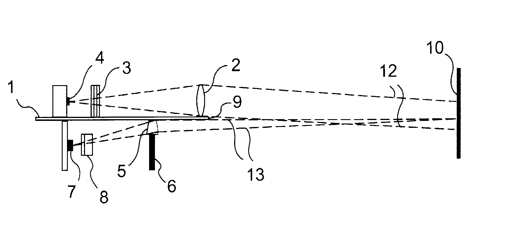
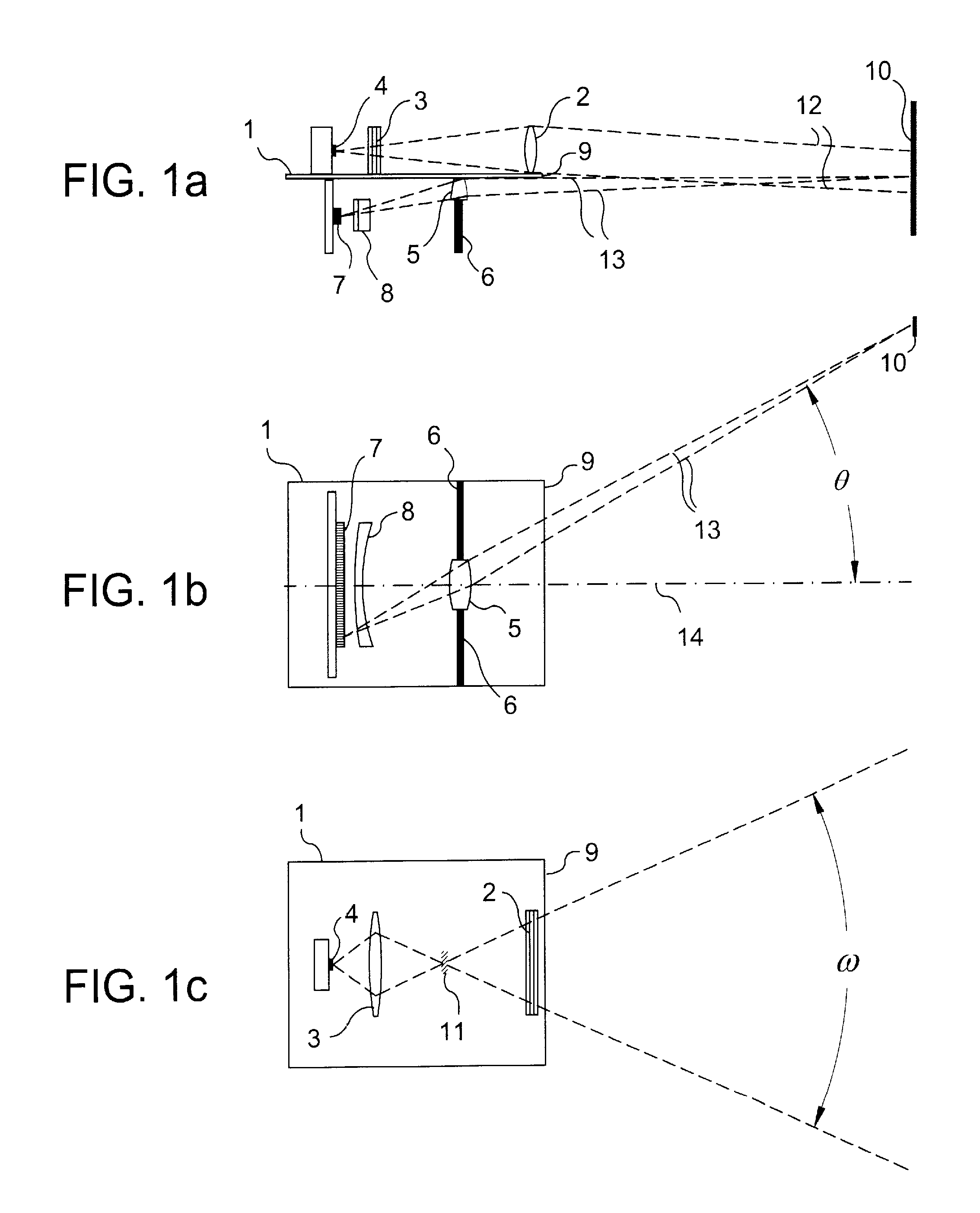
[0042]Referring to FIGS. 1a, 1b and 1c, the electro-optical sensor shown has a substrate 1 that separates a light-emitting assembly from a light-sensing assembly that are mounted on opposite sides of the substrate 1, and provides a light-screen between them. The light-emitting assembly in this case comprises a collimating lens 2, a parallel lens 3 and a light-emitting device in the form of an LED 4, whereas the light-sensing assembly comprises a collector lens 5, an aperture plate 6, a photodiode array 7 and (optionally) a field-curvature correcting lens 8. The lens 5, which has a rectangular rim, is located within the aperture of the plate 6 with one of its edges abutting the substrate 1 and the other three bounded by the aperture plate 6. In this way, the lens 5 provides the entrance pupil of the sensor since all light-rays incident on the photodiode array 7 pass through the lens.

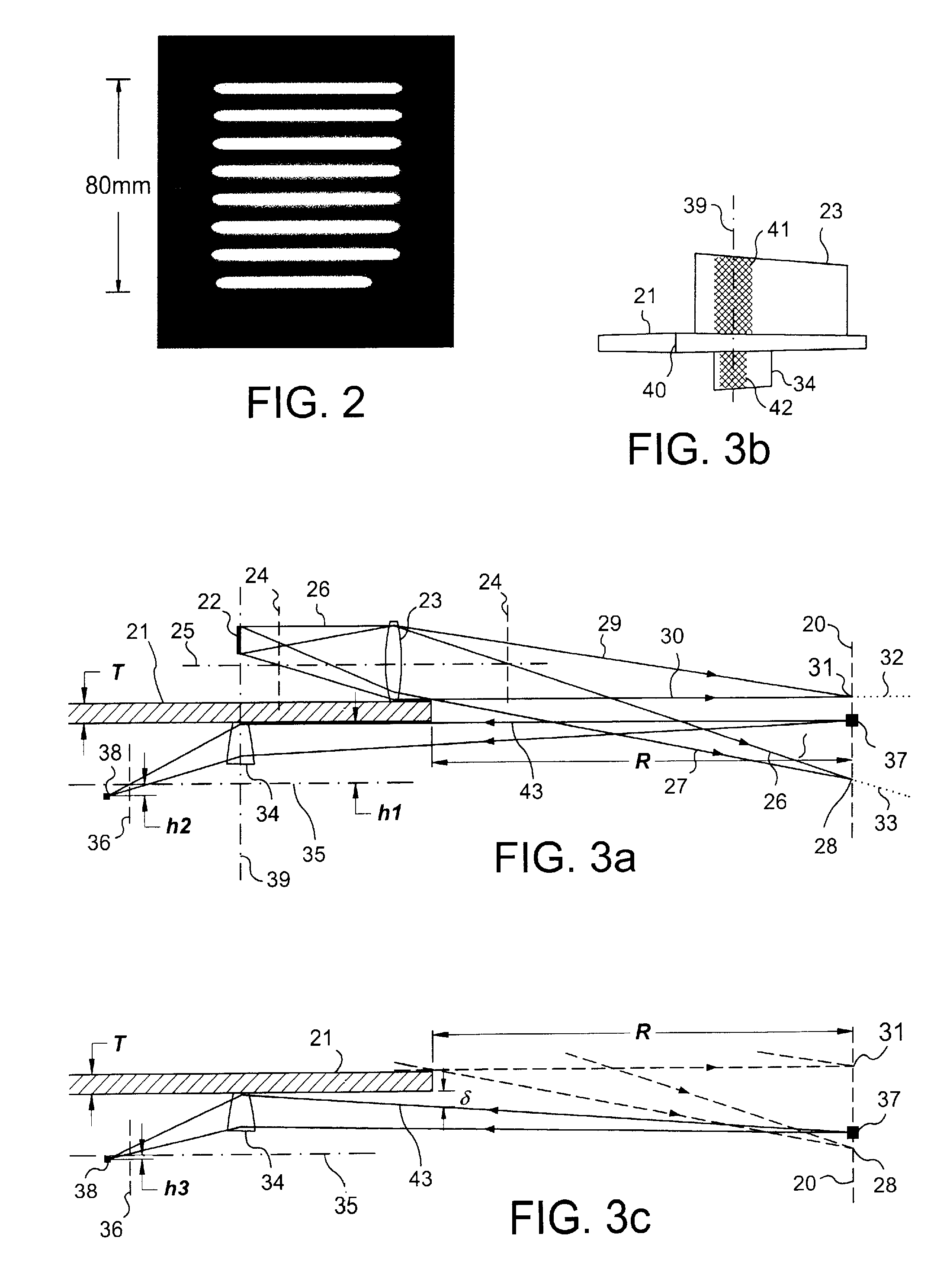
[0043]The substrate 1 is opaque and has thickness T, where Tis very small compared with the operating ...


PUM


Abstract

An electro-optical sensor for use with a retro-reflective target (10). The light-emitting assembly involves a LED (4) and collimating and parallel lenses (2, 4), and the sensing assembly involves a collecting lens (5), an aperture plate (6) and a photodiode array (7) with optional field-curvature correcting lens (8). The lens (5) abut the substrate (1) within the aperture of plate (6) so that the entrance pupil and the exit pupil, when viewed from the target (10), abut opposite, parallel straight-edges of the substrate (1). The photodiode array (7) may be a linear pixel array parallel to the substrate-surface, or may be replaced by a single, large-area photodiode with aperture-limitation of its field of view to a narrow fan-shape parallel to the substrate-surface. A plurality of light-emitters (77) may be used with photo-detectors (71) that have individual light-collection optics (72, 73) with merged fields of view. The sensor can sense golf club-head (100) movement and vehicle speed and plate number (116).

Description

[0001]This application is a National Stage completion of PCT / GB2008 / 001765 filed May 23, 2008, which claims priority from Great Britain patent application no. 0710129.8 filed May 26, 2007.FIELD OF THE INVENTION[0002]This invention relates to electro-optical sensors for use in the sensing of retro-reflective targets.SUMMARY OF THE INVENTION[0003]According to the present invention there is provided an electro-optical sensor comprising a light-emitter having co-acting light-projection optics for projecting a light beam from the light-emitter to illuminate a retro-reflective target at a location spaced from the sensor, and a photoelectric detector having co-acting light-collection optics, the photoelectric detector with its light-collection optics being located side by side with the light-emitter and its light-projection optics either side of an intervening light-screen, and wherein the light-collection optics focuses onto the photoelectric detector light of the light beam reflected ret...

Claims


Application Information

Patent Timeline
IPC IPC(8): G01J1/04H01L31/0232
CPCA63B69/3614G01S17/46A63B69/3658A63B2220/05A63B2220/13A63B2220/30A63B2220/35A63B2220/80A63B2220/803A63B2220/805A63B2220/833A63B2243/0029G01S7/4811G01S7/4814A63B69/3632A63B2102/32
Inventor LINDSAY, NORMAN MATHESON
Owner LINDSAY LTD
Why Eureka
Try Eureka