
Actuator for lifting device

a technology of actuating device and lifting rod, which is applied in the direction of lifting device, toothed gearing, gearing, etc., can solve the problems of lowering damage to the worm gear, and limited length of the retractable rod ab>4/b>, so as to enhance the performance of the actuator

Inactive Publication Date: 2010-06-10
MOTECK ELECTRIC CORP
View PDF6 Cites 26 Cited by
  • Summary
  • Abstract
  • Description
  • Claims
  • Application Information

AI Technical Summary

Benefits of technology

The present invention provides an actuator for lifting device that overcomes the shortcomings of prior art designs. The actuator includes a base, a motor, a gear set, a brake module, a linking rod assembly, a screw rod, a movable member, and an extension rod. The gear set and brake module are arranged in a parallel manner relative to the linking rod assembly, which maximizes the moving range of the movable block on the screw rod and enhances the performance of the actuator. The design also prevents damage to the brake module by effectively buffering any external force and ensuring the protruding strips of the stop device do not break or deform during rotation.

Problems solved by technology

1. Because the retractable rod A4, the spiral spring A3 and the worm gear A2 are arranged on one same path, the worm bear A2 occupies a part of the reciprocating path of the retractable rod A4. Thus, the length of the retractable rod A4 is limited, lowering the performance of the actuator.
2. The worm gear A2 is directly connected in series to one end of the retractable rod A4. When the retractable rod A4 receives an external pressure, the pressure will be directly transferred by the retractable rod A4 to the worm gear A2. If the worm gear A2 is held down by the spiral spring A3 at this time, direct transfer of the external pressure by the retractable rod A4 to the worm gear A2 may damage the worm gear A2 and the spiral spring A3.

Method used


Image

  • Actuator for lifting device
  • Actuator for lifting device
  • Actuator for lifting device

Examples


Embodiment Construction

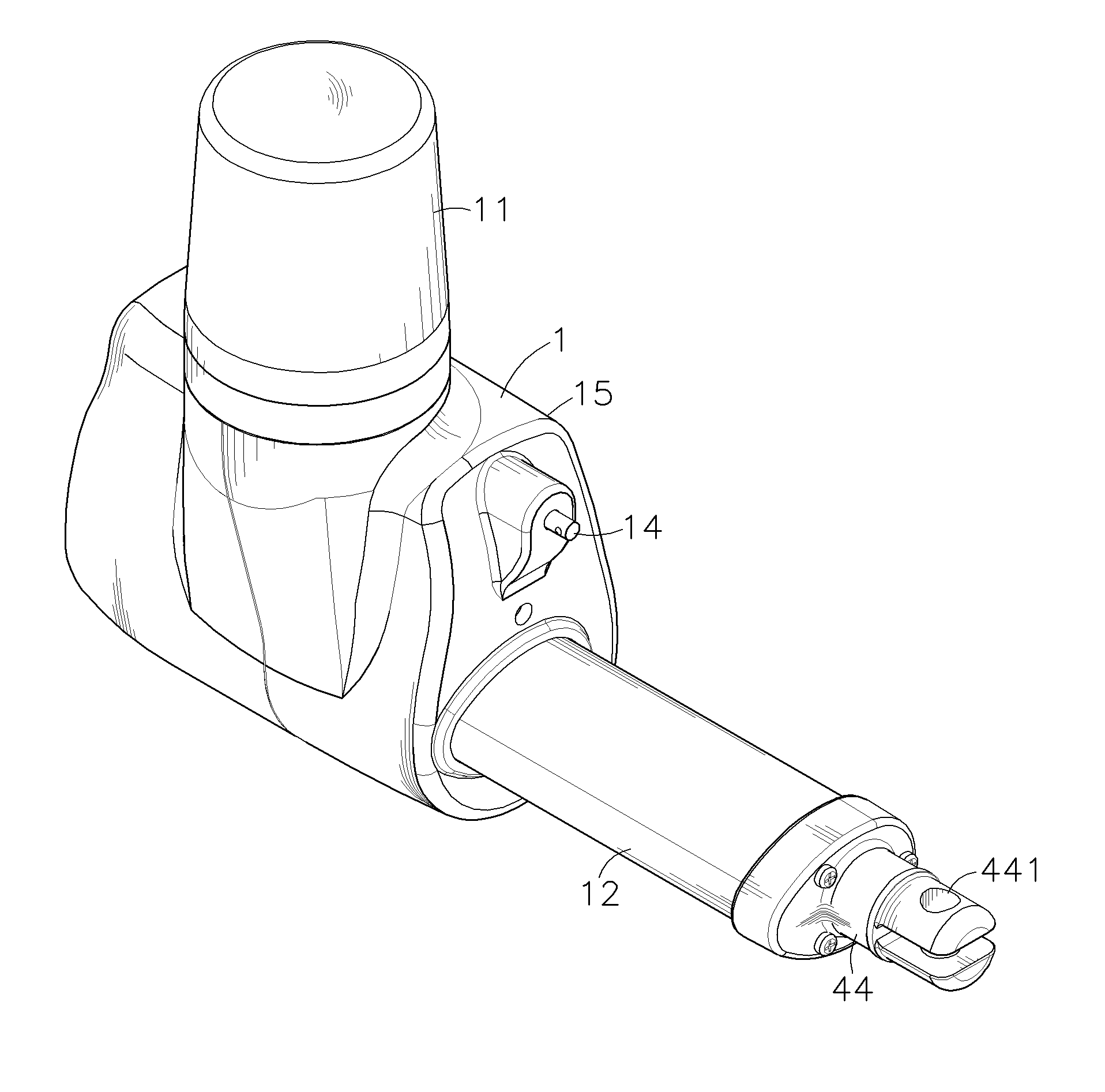
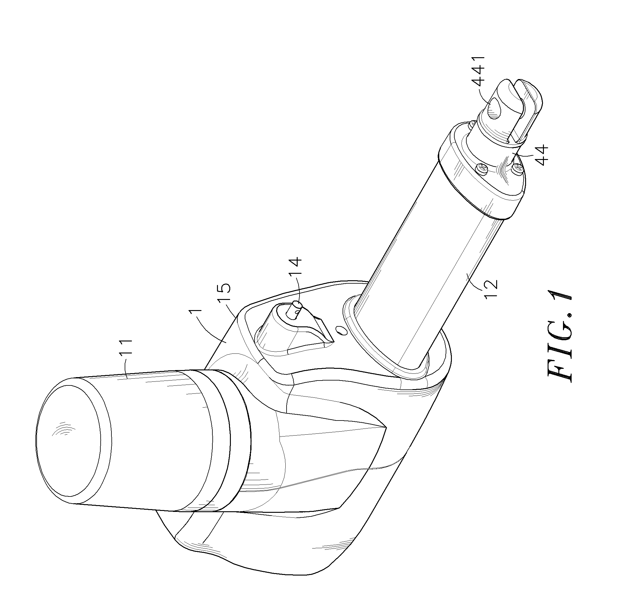
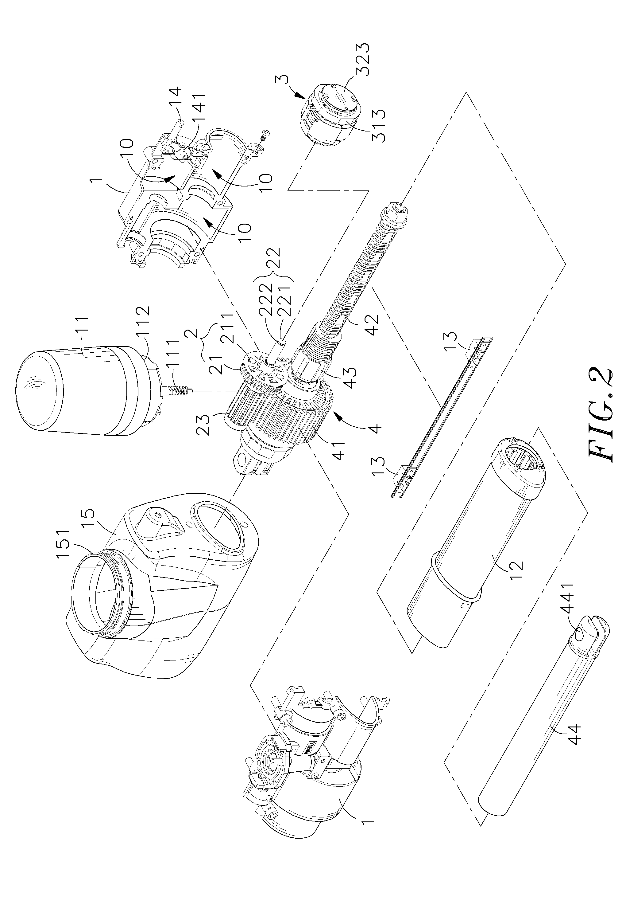
[0026]Referring to FIGS. 1˜5, an actuator for lifting device in accordance with the present invention is shown comprising a base 1, a transmission gear set 2, a brake module 3, and a linking rod assembly 4.

[0027]The base 1 is covered with a shell 15. Further, the base 1 holds a motor 11 on the top side thereof. The motor 11 is adapted to rotate a worm 111 that extends to an accommodation chamber 10 inside the base 1. Further, a sleeve 12 is affixed to the front side of the base 1. Further, two micro switches 13 are mounted in front and rear sides inside the sleeve 12.

[0028]The transmission gear set 2 comprises a gear shaft 22 pivotally mounted in the accommodation chamber 10, a worm gear 21 pivotally mounted on the gear shaft 22 and meshed with the worm 111, and an output gear 23 fixedly mounted on the gear shaft 22.

[0029]The brake module 3 is mounted on the gear shaft 22 of the transmission gear set 2, comprising a stop device 31 sleeved onto the gear shaft 22 and rotatable with th...


PUM


Abstract

An actuator includes a base, a motor mounted on the base for driving a worm to rotate a worm gear of a transmission gear set that is set in an accommodation chamber inside the base and has a gear shaft pivotally inserted through the worm gear and fixedly mounted with an output gear, a brake module rotatable with said worm gear, a linking rod assembly having a driven gear meshed with the output gear, a screw rod rotatable with the driven gear, a movable member threaded onto the screw rod and an extension rod connected to the movable block and movable in and out of a sleeved outside the base upon rotation of the screw rod for biasing a crane beam of a lifting device.

Description

[0001]This application claims the priority benefit of Taiwan patent application number 097221891 filed on Dec. 5, 2009.BACKGROUND OF THE INVENTION[0002]1. Field of the Invention[0003]The present invention relates to an actuator for lifting deice and more particularly, to such an actuator, which comprises a linking rod assembly for moving a lifting device, and a transmission gear set and a brake module arranged at one side of the linking rod assembly and rotatable by a motor to move the linking rod assembly in extending out or retracting an extension tube.[0004]2. Description of the Related Art[0005]A lifting device is a mechanism for changing the elevation of an object. Different lifting devices differently configured to fit different application requirements.[0006]FIG. 11 illustrates an actuator A for use in a lifting device. As illustrated, the actuator A comprises an electric motor A1 having a worm A11 fixedly connected to the output shaft thereof, a worm gear A2 meshed with the ...

Claims


Application Information

Patent Timeline
Patent Type & Authority Applications(United States)
IPC IPC(8): F16H25/20
CPCB66F3/08F16H25/2454F16H2025/2084Y10T74/18696Y10T74/18576Y10T74/18688Y10T74/18704F16H2025/209
Inventor KU, CHENG-HU
Owner MOTECK ELECTRIC CORP
Learn More