
Outer stator of reciprocating engine and reciprocating engine

a technology of outer stator and reciprocating engine, which is applied in the direction of electrical apparatus, dynamo-electric machines, etc., can solve the problems of difficulty in achieving any further improvement in the output of the reciprocating engine, and achieve the effects of improving the capacity of the wound wire coil, suppressing the generation of leakage magnetic paths, and improving outpu

Inactive Publication Date: 2010-06-10
DIAMET CORP
View PDF6 Cites 2 Cited by
  • Summary
  • Abstract
  • Description
  • Claims
  • Application Information

AI Technical Summary

Benefits of technology

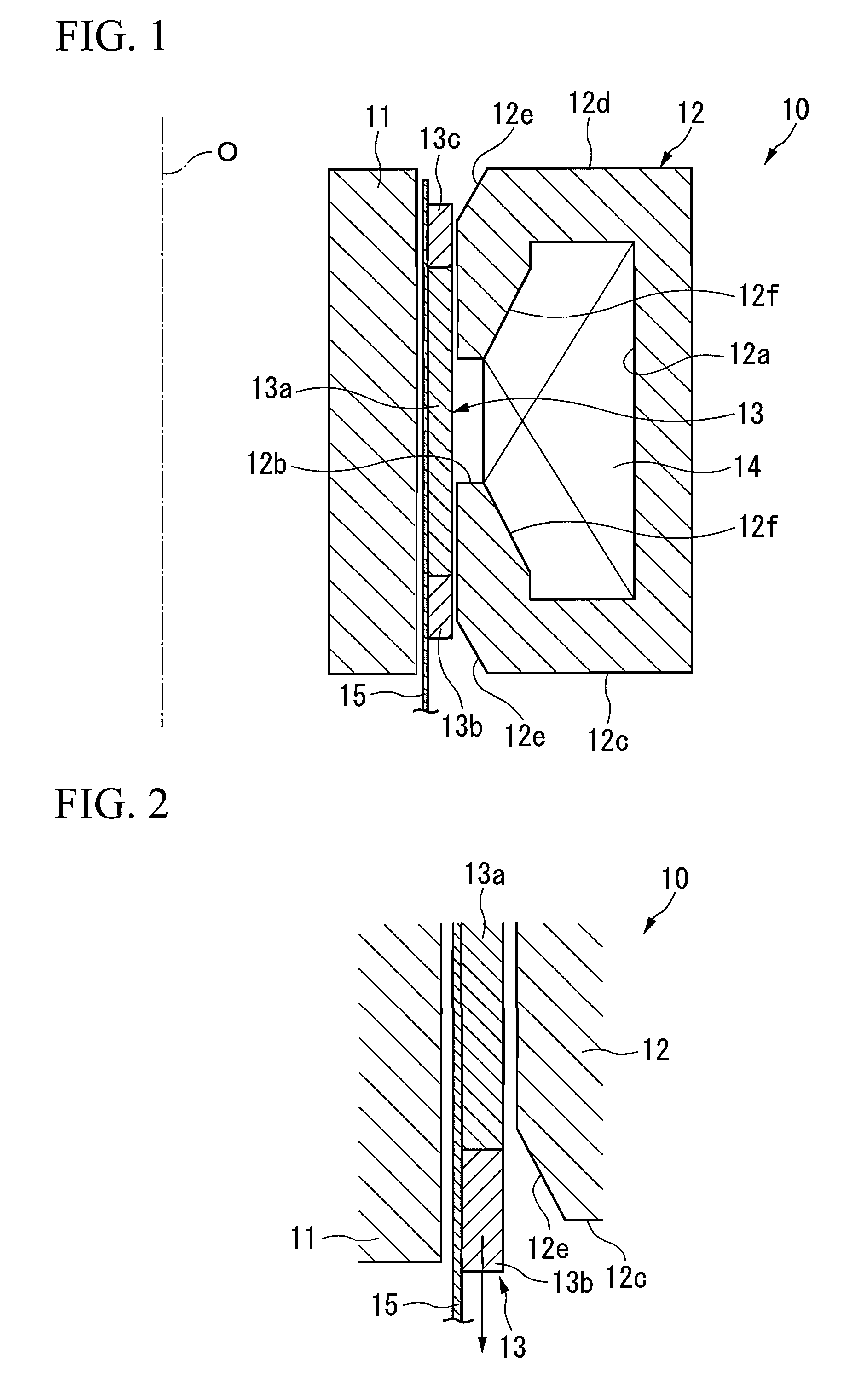
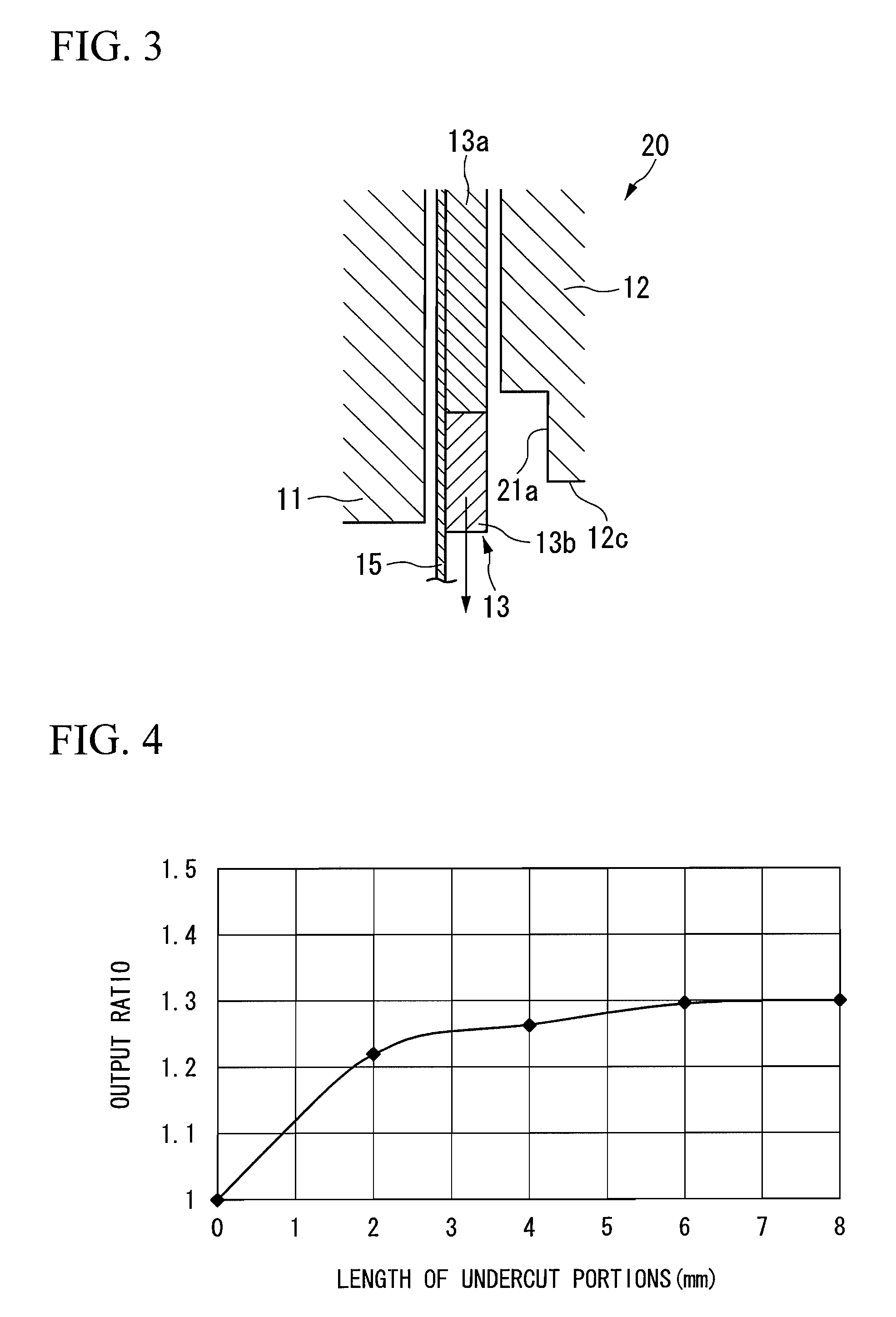
The present invention provides an outer stator for a reciprocating engine and a reciprocating engine that can improve output. The outer stator has an aperture portion, an internal space where a wound wire coil is placed, and undercut portions that prevent leakage magnetic paths. The mover has restoring magnet portions that face the undercut portions when the load on the engine is at maximum, suppressing the generation of a leakage magnetic path and improving the output of the engine. The outer stator can also have an expanding space portion to increase the capacity of the wound wire coil and further improve the engine's output.

Problems solved by technology

Because a leakage magnetic path G1 is generated in a portion of this magnetic path G that flows via the first restoring magnet portion 103b and the second restoring magnet portion 103c towards the inner stator 101, the problem exists that it is difficult to achieve any further improvement in the output of the reciprocating engine 100.

Method used


Image

  • Outer stator of reciprocating engine and reciprocating engine
  • Outer stator of reciprocating engine and reciprocating engine
  • Outer stator of reciprocating engine and reciprocating engine

Examples


Embodiment Construction

[0024]Embodiments of this invention will be described below with reference to the drawings.

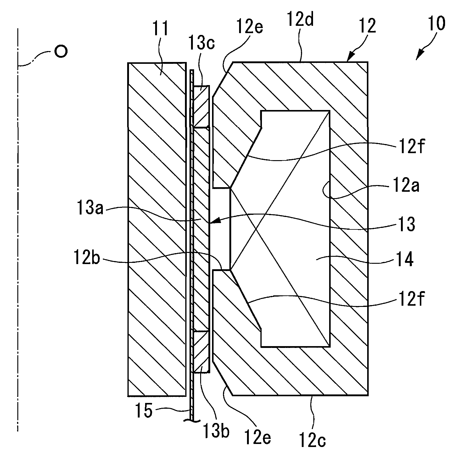
[0025]Firstly, the schematic structure of a reciprocating engine 10 in which the outer stator according to the present embodiment is provided will be described. This reciprocating engine 10 is used in a variety of types of electrical generator and has the structure shown in FIG. 1. Namely, a mover 13 and an outer stator 12 that are each formed in a cylindrical shape are fitted in this sequence from an inner side in the radial direction towards an outer side thereof coaxially around a toroidal or columnar inner stator 11. Namely, an outer circumferential surface of the mover 13 and an inner circumferential surface of the outer stator 12 face each other, and an inner circumferential surface of the mover 13 and an outer circumferential surface of the inner stator 11 are positioned so as to face each other via a metal tube 15 (described below). In other words, the outer stator 12 is fitted around ...


PUM


Abstract

An outer stator is provided in a reciprocating engine together with an inner stator and a mover, that has a cylindrical shape and is placed around the mover coaxially with an axis of the mover, and that forms a magnetic path between itself and the inner stator via a field magnet of the mover, the outer stator includes an aperture portion that is formed in an inner circumferential surface thereof that faces the mover; an internal space that opens via the aperture portion, and in which a wound wire coil is placed; and undercut portions that, in a cross section including the axis, are provided at both end positions along the axis, and that are recessed from the inner circumferential surface towards the outer side in a radial direction.

Description

CROSS REFERENCE TO RELATED APPLICATIONS[0001]This is a U.S. national phase application under 35 U.S.C. §371 of International Patent Application No. PCT / JP2006 / 314766, filed Jul. 26, 2006. Priority is claimed on Japanese Patent Application No. 2005-221744, filed Jul. 29, 2005. The International Application was published on Feb. 1, 2007 as International Publication No. WO 2007 / 013506 under PCT Article 21(2) the contents of which are incorporated herein in their entirety.TECHNICAL FIELD[0002]The present invention relates to an outer stator for a reciprocating engine and to a reciprocating engine.BACKGROUND OF THE INVENTION[0003]Conventionally, reciprocating engines are used in driving apparatuses and electrical generators and the like. For example, the Stirling cycle engine illustrated in Japanese Unexamined Patent Application, First Publication No. 2004-293829 described below is known as an example of the driving apparatus.[0004]A structure such as that shown in FIG. 5 is known as a r...

Claims


Application Information

Patent Timeline
Patent Type & Authority Applications(United States)
IPC IPC(8): H02K33/16
CPCH02K35/02H02K33/16
Inventor MIYAHARA, MASAHISAKANAGAWA, KINJI
Owner DIAMET CORP
Learn More