
Method and device for analyzing electric cable networks

a technology of electric cables and networks, applied in the direction of electrical testing, transmission, instruments, etc., can solve the problems of less advantageous solutions, and achieve the effect of reducing the number of multiple reflections

Inactive Publication Date: 2010-06-10
COMMISSARIAT A LENERGIE ATOMIQUE ET AUX ENERGIES ALTERNATIVES
View PDF4 Cites 19 Cited by
  • Summary
  • Abstract
  • Description
  • Claims
  • Application Information

AI Technical Summary

Benefits of technology

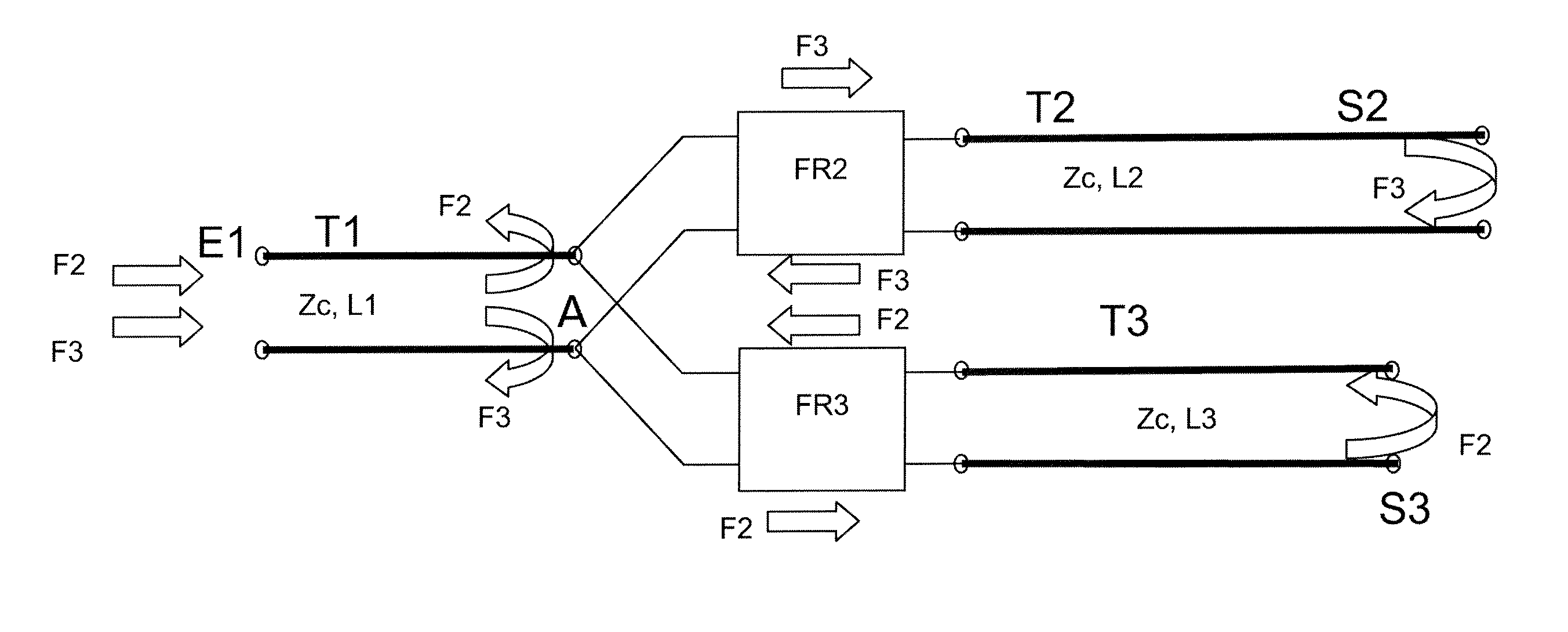
[0020]With this method, it is possible to extract a non-ambiguous item of information about the position of a defect in a network cable having one or more branch-offs. A defect on a stretch is in fact located on the basis of a reflected signal which does not contain, at a given instant, the characteristic frequency related to this stretch; this defect can thus be distinguished from the defects present on another stretch and from the ends of these other stretches. The presence of the filters reduces the number of multiple reflections which tend, in the prior art, to make it difficult to utilize the reflectograms generated.

Problems solved by technology

The latter solution is however less advantageous since it generates several distinct response charts that must subsequently be reconciled.

Method used


Image

  • Method and device for analyzing electric cable networks
  • Method and device for analyzing electric cable networks
  • Method and device for analyzing electric cable networks

Examples


Embodiment Construction

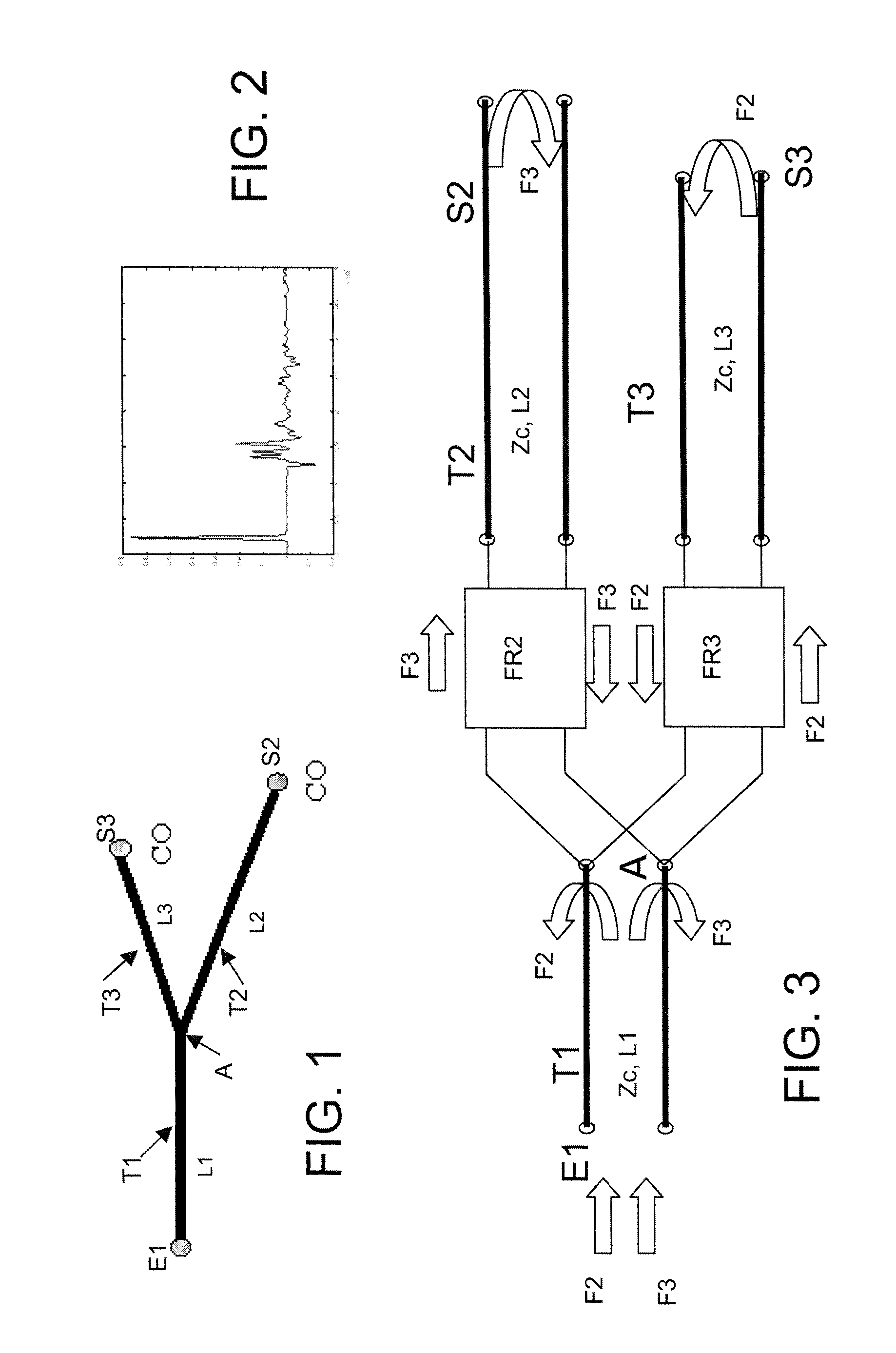
[0042]Schematically represented in FIG. 1 is a network with one junction and two branch-offs, having three stretches T1, T2 and T3. The stretches T2 and T3 have an input end linked to a junction point A situated at an output end of the stretch T1. Thus, if the network is followed starting from an input end E1 thereof, one successively encounters a cable length L1 of the stretch T1, then a junction at A, and, depending on whether one is following the stretch T2 or the stretch T3, respectively a cable length L2 of the stretch T2 up to its output end S2, or a cable length L3 of the stretch T3 up to its output end S3.

[0043]This is a simple example of a T-network (or Y-network). The stretches considered and represented by a line can consist of a sheathed conducting wire or a pair of sheathed wires or a coaxial cable. This network can serve either to transport energy or communication signals from the input E1 to the outputs S2 and S3, or in the opposite direction from one output S2 or S3 ...


PUM


Abstract

The invention relates to a method and a device for analyzing electric cables in a network, for the detection and location of defects in networks comprising at least one junction from which there depart N secondary cable stretches. The method includes interposing in the network, in series at the input of each the secondary stretches (T2, T3) starting from the junction (A), a respective bidirectional passive filter (FR2,FR3) able to cut off a frequency band associated with this stretch. The filters all allow through the useful frequencies for the normal operation of the network. A pulsed test is applied to the input of the network signal modulated by N different carrier frequencies each situated in one of the N frequency bands of the filters. The temporal position of test signal spikes reflected for each of the N frequencies is detected, and deducing therefrom the position of possible defects on a stretch of cable of the network.

Description

CROSS-REFERENCE TO RELATED APPLICATIONS[0001]The present Application is based on International Application No. PCT / EP2007 / 056834, filed on Jul. 5, 2007, which in turn corresponds to French Application No. 0606531, filed on Jul. 18, 2006, and priority is hereby claimed under 35 USC §119 based on these applications. Each of these applications are hereby incorporated by reference in their entirety into the present application.FIELD OF THE INVENTION[0002]The invention relates to a method and a device for analyzing electric cables in a network, for the detection and location of defects in the cables of this network.[0003]The electric cables concerned may be energy transmission cables or communication cables, in fixed installations (distribution network, indoor or outdoor communication network) or mobile installations (energy or communication network in an airplane, a boat, an automobile, etc.). The cables concerned may be any: coaxial or bifilar, in parallel lines or in twisted pairs, sh...

Claims


Application Information

Patent Timeline
IPC IPC(8): G01R31/11
CPCG01R31/11
Inventor RAVOT, NICOLASCOHEN, JOSYCHAMBAUD, PASCAL
Owner COMMISSARIAT A LENERGIE ATOMIQUE ET AUX ENERGIES ALTERNATIVES
Learn More