Stereo video microscope system

a video microscope and microscope technology, applied in the field of stereo video microscope systems, can solve the problems of rotating the image and even the image being displayed, being rather dissatisfactory for the medical professional or the patient, and being often very inconvenien

Inactive Publication Date: 2010-06-10
SWISS MEDICAL TECH
View PDF18 Cites 6 Cited by
  • Summary
  • Abstract
  • Description
  • Claims
  • Application Information

AI Technical Summary

Problems solved by technology

This, however, is often very inconvenient, because of the awkward positions the medical professional has to place himself in, in order to be able to look through the eye-pieces of the stereo microscope and to work with his hands within the region of interest.
Obviously, such a situation is rather dissatisfying for the medical professional or the patient being examined and / or treated.
However, conventional stereo microscopes with a fixed stereo base have the problem that a change of the position of the microscope can lead to a rotation of the image and even to the image being displayed upside down.
Again, such a situation is rather confusing and, consequently, dissatisfying for the medical professional using a conventional stereo microscope.
However, using a mirror in combination with a stereo microscope involves additional challenges in that any light coming from the parts of the dental region of a patient being examined with a mirror will experience one additional interaction with the mirror (i.e. a reflection) before entering the stereo microscope.
Conventional stereo microscopes do not have any means for compensating for such an effect.
In the latter case only a small part of the light emitted by the internal lighting of the microscope is actually “used”, whereas the bulk thereof is being wasted.
This, in turn, leads to a difficult, if not impossible fine adjustment of the focus distance at high magnifications in conventional stereo microscopes.
However, as already outlined further above, a medical professional and especially a dentist often will need to examine regions which are difficult to illuminate and, thus, to image by conventional stereo microscopes having a fixed internal lighting.
Obviously, this situation is dissatisfying for the medical professional.
The separate support systems of the microscope and the external light source are prone to colliding and interfering with each other and, consequently, it is often very difficult to manipulate and adjust these separate elements for providing an optimal internal and external illumination.
Again, such a situation is rather dissatisfying for the medical professional using a conventional microscope together with an external light source.

Method used


Image

  • Stereo video microscope system
  • Stereo video microscope system
  • Stereo video microscope system

Examples


Embodiment Construction

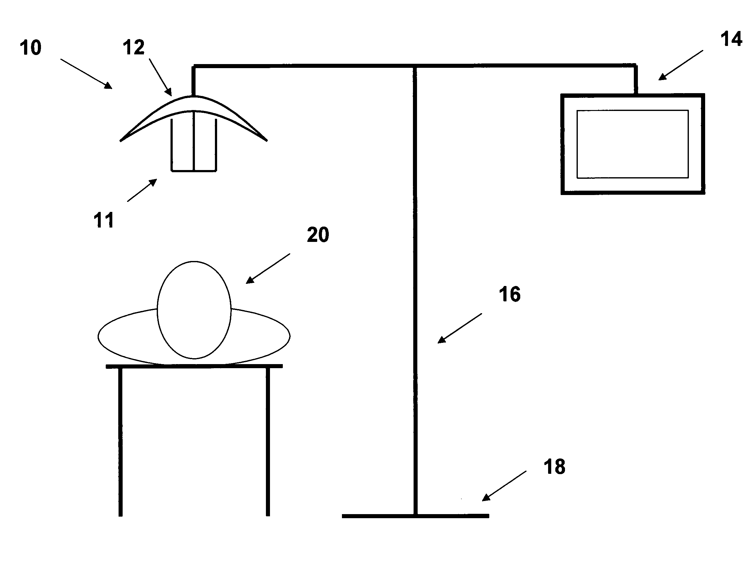
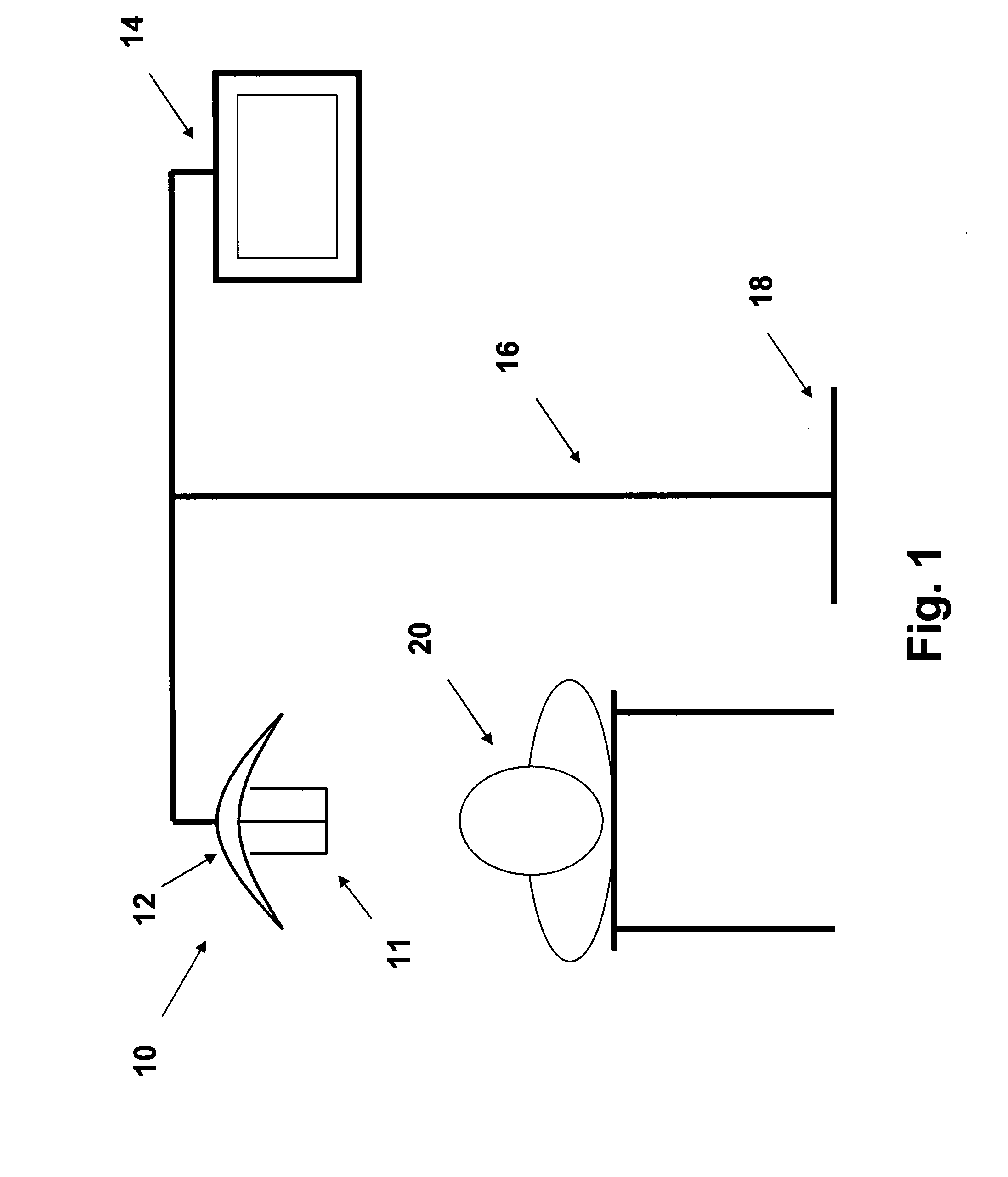
[0013]A preferred embodiment of the stereo video microscope system 10 according to the present invention is shown in FIG. 1. The stereo video microscope system 10 comprises a stereo video microscope 11 which in addition to its own internal lighting (not shown) is embedded within an external lighting unit 12. A stereo video microscope 11 which suitably can be employed in the stereo video microscope system 10 according to the present invention is described, for instance, in EP 05 026 775 (assigned to the same applicant as the present application).

[0014]The stereo video microscope 11 and the external lighting unit 12 are mounted to a common support structure 16. Although the support structure 16 is shown in FIG. 1 as fixedly mounted to a base 18 resting on the floor, the support structure 16 equally could be fixedly mounted to a wall or a ceiling. Also, the support structure 16 could be resting on a movable base 18 such that the stereo video microscope system 10 according to the presen...


PUM


Abstract

A stereo video microscope system (10), comprising: a stereo video microscope (11) having two output channels for providing stereo image data and including an internal lighting; a display unit (14) having two input channels for receiving and displaying stereo image data; and a control unit operably connected to the stereo video microscope (11) and the display unit (14) such that the control unit can control the operation of the stereo video microscope (11) and the display unit (14) and the flow of stereo image data between the two output channels of the stereo video microscope (11) and the two input channels of the display unit (14). In one embodiment the control unit is configured for performing an image rotation and / or exchanging the output channels such that the stereo image is always upright.

Description

TECHNICAL FIELD OF THE INVENTION[0001]The invention relates to a stereo video microscope system and in particular to a stereo video microscope system to be employed by medical professionals and especially dentists and surgeons.BACKGROUND OF THE INVENTION[0002]In the medical field it is becoming more and more common practice to use stereo microscopes for assisting medical professionals in performing such tasks as medical surgeries, examinations, treatments and the like. The medical professional using a conventional stereo microscope has to look through the eye-pieces thereof in order to study a region of interest. This, however, is often very inconvenient, because of the awkward positions the medical professional has to place himself in, in order to be able to look through the eye-pieces of the stereo microscope and to work with his hands within the region of interest. Obviously, such a situation is rather dissatisfying for the medical professional or the patient being examined and / o...

Claims


Application Information

Patent Timeline
Patent Type & Authority Applications(United States)
IPC IPC(8): H04N13/02H04N13/04
CPCG02B21/22G02B21/0012
Inventor LUBER, JOACHIMJANIK, STEFFEN-VOLKER
Owner SWISS MEDICAL TECH
Why Eureka
Try Eureka