
Scanner and image forming apparatus including the same

a technology of scanning apparatus and scanning lens, which is applied in the direction of instruments, electrographic processes, optical elements, etc., can solve the problems of unidirectional scanning, noise, and other problems, and achieve the effect of not being able to achieve unidirectional scanning and improving scanning speed

Inactive Publication Date: 2010-06-10
S PRINTING SOLUTION CO LTD
View PDF1 Cites 46 Cited by
  • Summary
  • Abstract
  • Description
  • Claims
  • Application Information

AI Technical Summary

Benefits of technology

[0025]The mirror may oscillate about the first axis so as to cause the light incident upon the reflective surface thereof to be deflected across a substantially linear scanned path. A first scanned path of the light deflected by the mirror when the mirror is rotat

Problems solved by technology

The use of a spindle motor, however, may cause vibration, noise, and other problems.
Moreover, when a polygon mirror is used, only a unidirectional scanning is possible and the scanning speed is not optimal.

Method used


Image

  • Scanner and image forming apparatus including the same
  • Scanner and image forming apparatus including the same
  • Scanner and image forming apparatus including the same

Examples


Embodiment Construction

[0038]Reference will now be made in detail to the embodiment, examples of which are illustrated in the accompanying drawings, wherein like reference numerals refer to like elements throughout. While the embodiments are described with detailed construction and elements to assist in a comprehensive understanding of the various applications and advantages of the embodiments, it should be apparent however that the embodiments may be carried out without those specifically detailed particulars. Also, well-known functions or constructions will not be described in detail so as to avoid obscuring the description with unnecessary detail. It should be also noted that in the drawings, the dimensions of the features are not intended to be to true scale and may be exaggerated for the sake of allowing greater understanding.

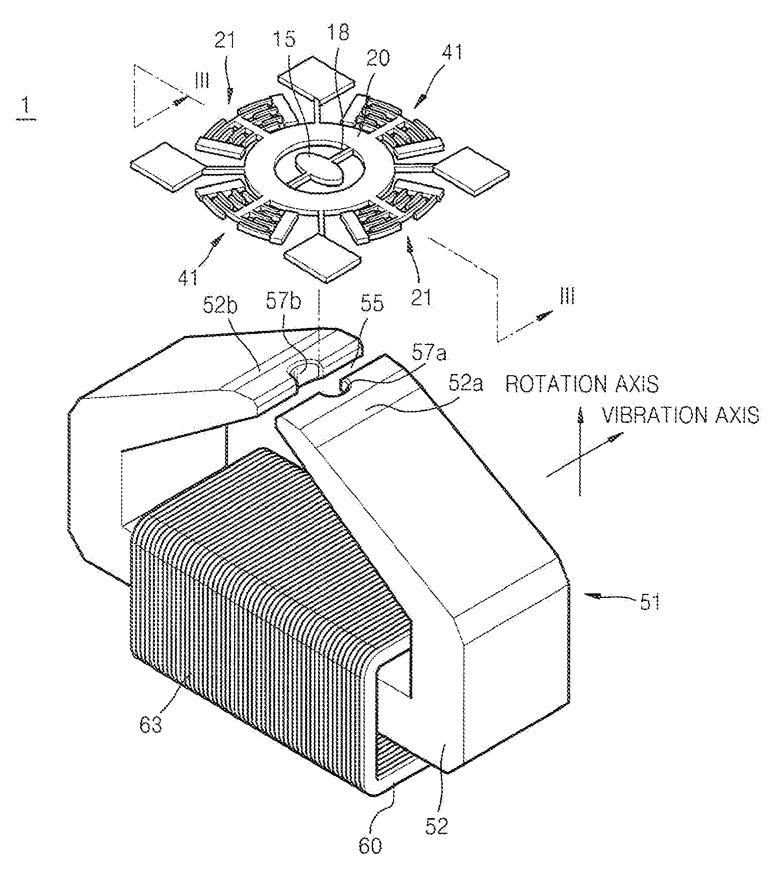
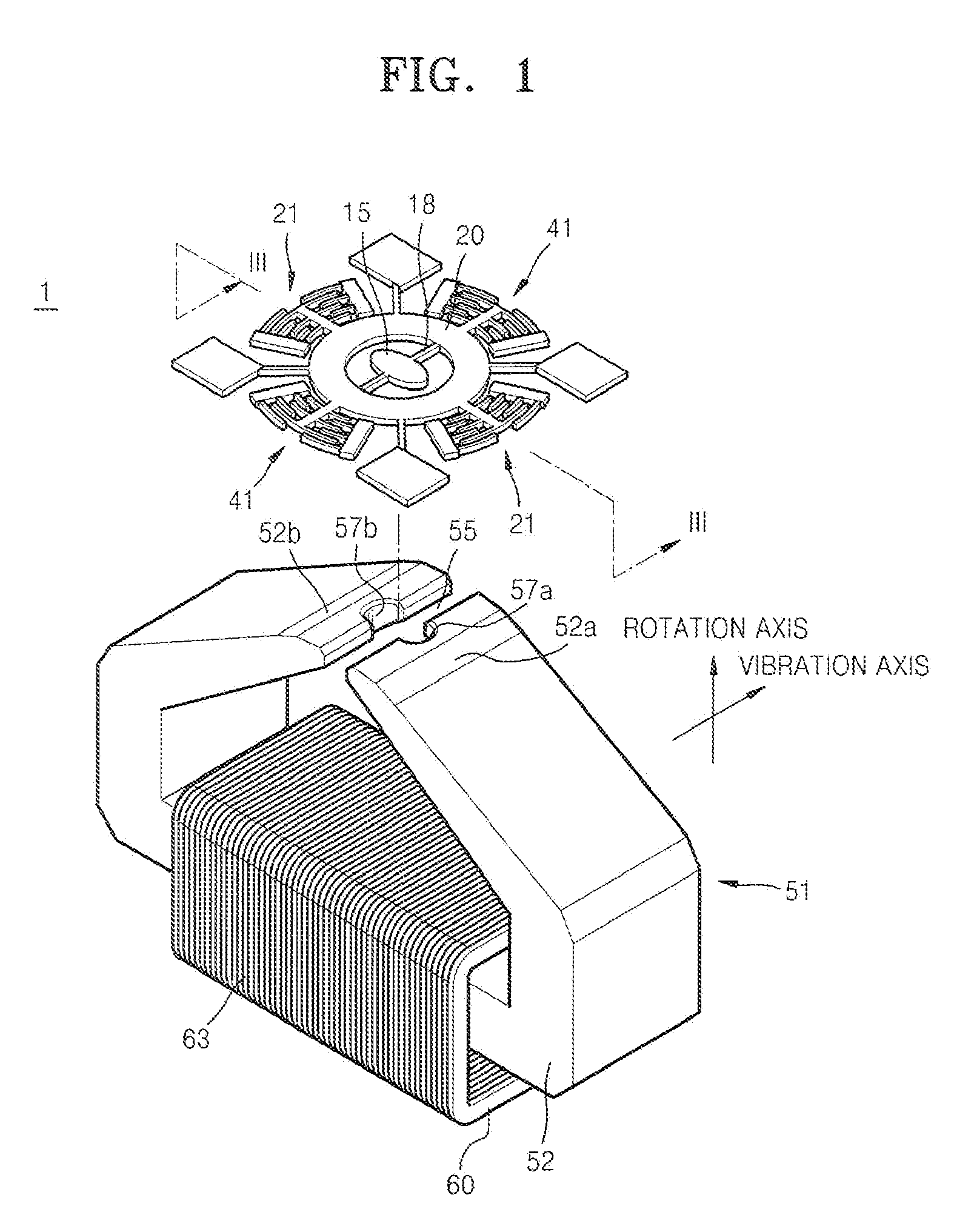
[0039]FIG. 1 is a perspective view of a scanner 1 according to an embodiment.

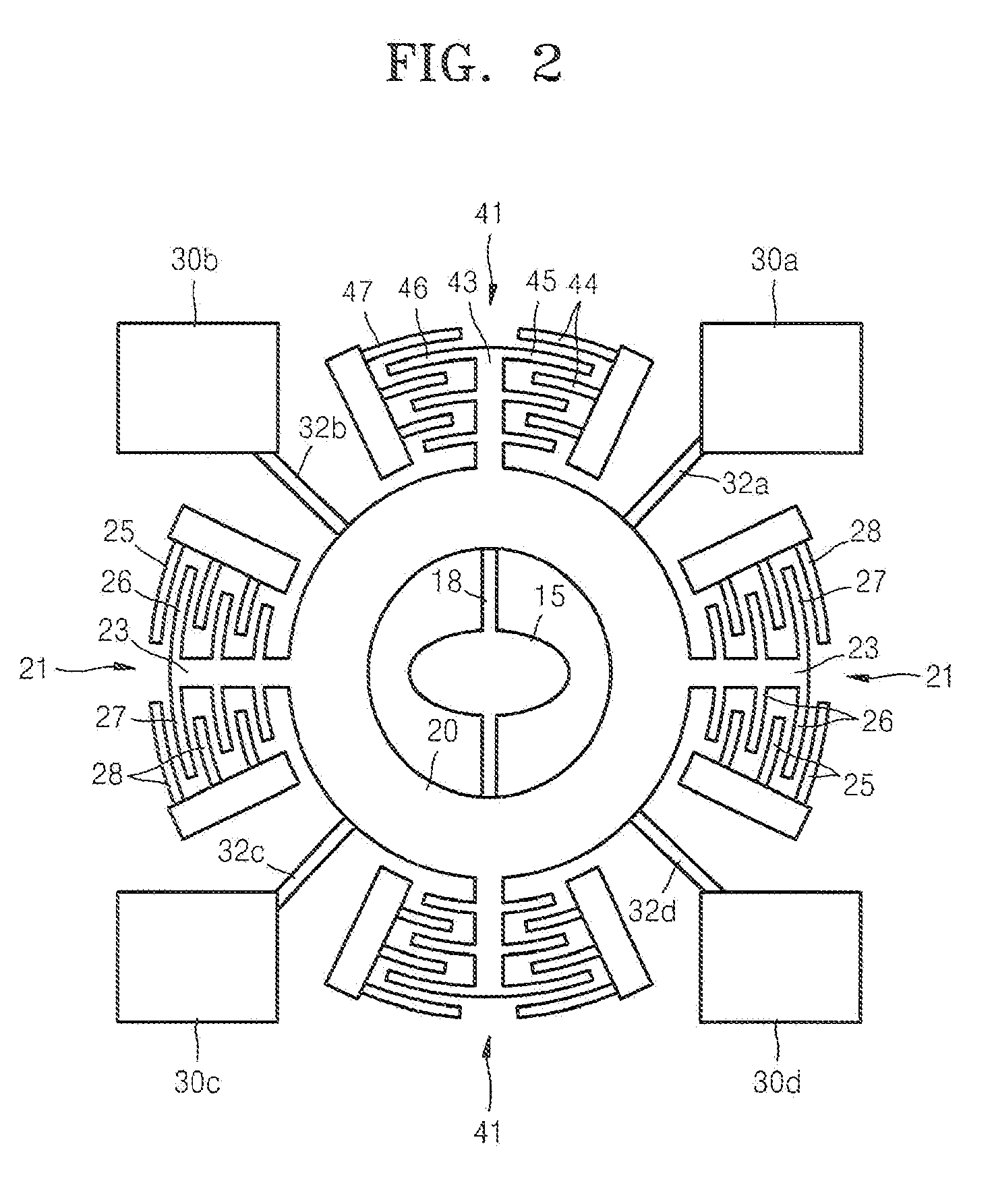
[0040]The scanner 1 may include a mirror 15 configured to deflect a light beam, a rotational body 20...


PUM


Abstract

Disclosed are a scanner and an image forming apparatus employing the same. The scanner may produce bidirectional scanning of light by oscillating a deflecting mirror about a first axis substantially parallel to the mirror surface, and may compensate for skewing of the scan lines by rotating the mirror about a second axis that is substantially perpendicular to the first axis so as to allow the light to be scanned at an angle.

Description

CROSS-REFERENCE TO RELATED PATENT APPLICATION[0001]This application claims the benefit of Korean Patent Application No. 10-2008-0122391, filed on Dec. 4, 2008, in the Korean Intellectual Property Office, the disclosure of which is incorporated herein by reference in its entirety.TECHNICAL FIELD[0002]The present disclosure relates generally to a scanner and an image forming apparatus including the same.BACKGROUND OF RELATED ART[0003]Beam scanning techniques for scanning a light beam emitted from a light source on a certain region of an object to be scanned may be applied in various devices such as, for example, image forming apparatuses and display devices. Beam scanning techniques may be important in improving the image quality of image forming apparatuses or displays, for example. A beam scanning unit of an image forming apparatus may include a polygon mirror that is rotationally driven by a spindle motor. The use of a spindle motor, however, may cause vibration, noise, and other p...

Claims


Application Information

Patent Timeline
IPC IPC(8): G02B26/08
CPCG02B26/0841G02B26/085G02B26/105G02B26/127H04N1/06H04N1/113H04N2201/04755H04N2201/0468H04N2201/04789H04N2201/02441H04N2201/04796G02B26/0833G03G15/00G06V10/10G02B26/101
Inventor KIM, SE-TAE
Owner S PRINTING SOLUTION CO LTD
Learn More