Optical resonance analysis unit

A technology of optical analysis and light source, which is applied to the analysis of materials, material analysis through optical means, instruments, etc., and can solve problems such as image walking that cannot be completely solved

Inactive Publication Date: 2007-08-22
GE HEALTHCARE BIO SCI CORP
View PDF0 Cites 11 Cited by
  • Summary
  • Abstract
  • Description
  • Claims
  • Application Information

AI Technical Summary

Problems solved by technology

While achieving the goal of correcting for simple defocus found in static non-normal angles of incidence SPR imaging systems, it does not fully resolve images acquired over the wide range of incidence angles required for array sensors with significant dynamic range" walk" problem

Method used


Image

  • Optical resonance analysis unit
  • Optical resonance analysis unit
  • Optical resonance analysis unit

Examples


Embodiment Construction

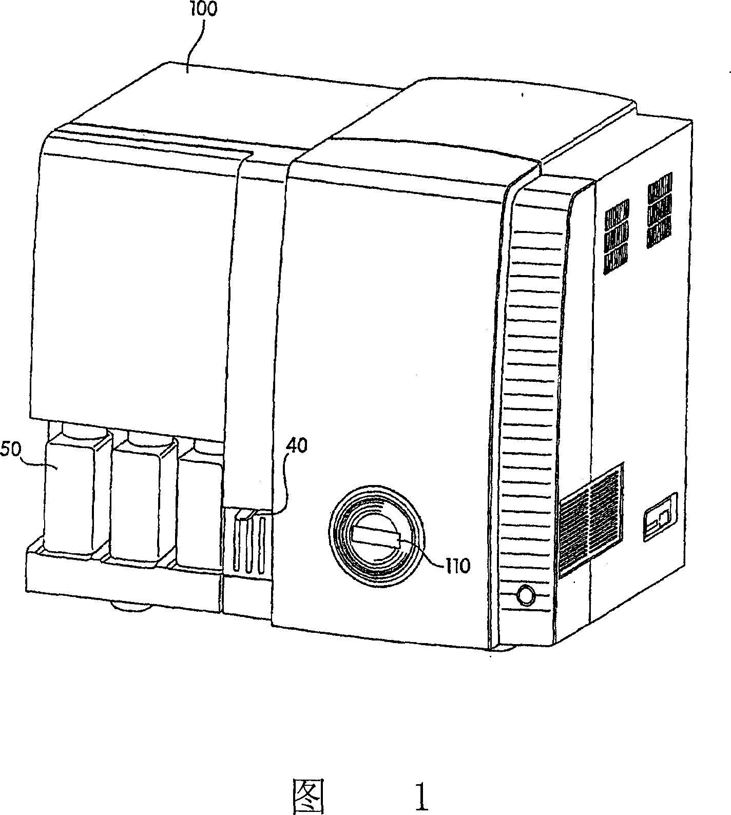
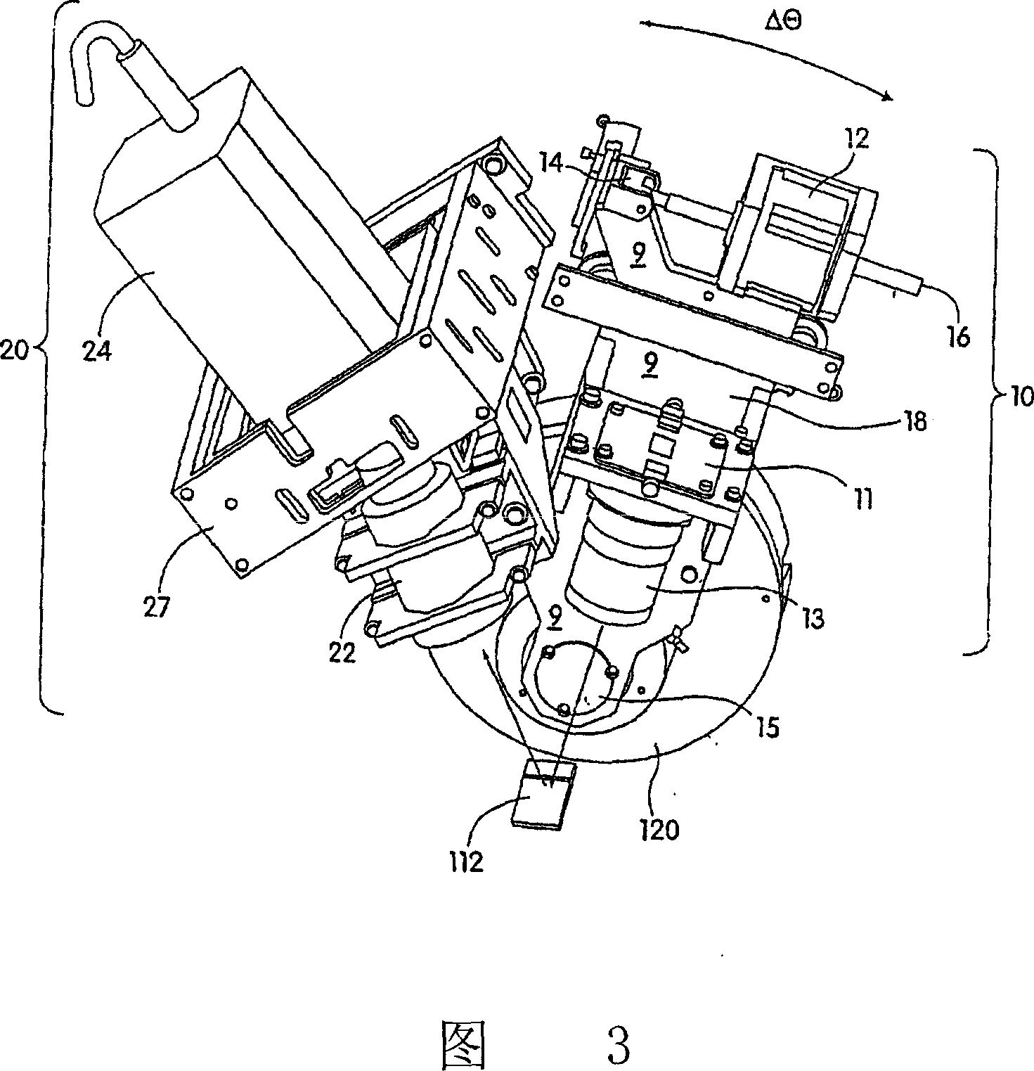
[0053] The present invention is directed to an improved optical resonance analyzer, especially for grating-coupled surface plasmon resonance (GCSPR), capable of simultaneously measuring reactive field arrays. In particular, the present invention combines a number of features that, in addition to allowing real-time analysis of up to thousands of molecular binding interactions, provide improvements in the control of reaction parameters including: system fluid control, temperature control, sensor scanning, and data collection and analysis from scanned sensors.

[0054] The analytical device may be fully automated, with all optical scanning operations controlled and performed automatically by software contained within the device. Essentially, once buffers, samples, and sensors are loaded into the device, the user can enter experimental parameters, such as time, temperature, fluid flow rate, etc., into a computer connected to the device, which can be programmed to Perform all assa...


PUM


Abstract

An optical analysis unit especially suitable for performing grating coupled surface plasmon resonance (SPR) imaging features a pivoting light source capable of scanning through a range of angles of incident light projected onto a stationary target sensor, such as an SPR sensor. The reflected image from the illuminated sensor is detected, e.g., by a CCD camera and the image and angular scan data are processed, for example by a fitting algorithm, to provide real time analysis of reactions taking place on the surface of the sensor.

Description

[0001] Related Application Cross Reference [0002] This application claims priority to US Provisional Application Nos. 60 / 492,061 and 60 / 492,062, both filed August 1, 2003, the disclosures of which are incorporated herein by reference. field of invention [0003] The present invention generally relates to optical resonance analysis systems. In particular, the present invention relates to an improved instrument for performing grating-coupled surface-plasmon resonance imaging using illumination and a detection system for real-time analysis of multiple reactions occurring on a sensor array surface. Background of the invention [0004] The basic working principle of grating-coupled surface-plasmon resonance (GCSPR) takes advantage of the surface charge vibrations produced when light of a certain wavelength hits a metal surface. For example, sensor chips typically consisting of plastic gratings coated with thin layers (~80 nm) of highly reflective metals (eg gold) are configure...

Claims


Application Information

Patent Timeline
Patent Type & Authority Applications(China)
IPC IPC(8): G01N21/55
CPCG01N21/553
Inventor D·H·特雷西J·M·布洛克曼K·S·费拉拉M·申克R·克尔斯坦S·E·科恩G·鲍德雷P·涂克斯布瑞P·赫德林顿E·皮科萨
Owner GE HEALTHCARE BIO SCI CORP
Why Eureka
Try Eureka