Microscopy method and device for controlled high-speed chromatography phase position

A high-speed layer and phase technology, applied in the field of optical super-resolution microscopy, can solve the problems of single control and insufficient data acquisition speed, and achieve the effects of stable system, strong controllability, improved sampling speed and operation controllability

Inactive Publication Date: 2014-04-23
ZHEJIANG UNIV
View PDF4 Cites 11 Cited by
  • Summary
  • Abstract
  • Description
  • Claims
  • Application Information

AI Technical Summary

Problems solved by technology

The use of acousto-optic modulators limits the data acquisition frequency of the entire system, and the control of the entire system becomes single. At the same time, the data acquisition speed of 10 frames per second is still not enough for observing rapidly changing biological activity cells, so a stable, Controllable, high-speed tomographic phase microscopy is a meaningful breakthrough in micro-optical imaging and life sciences

Method used


Image

  • Microscopy method and device for controlled high-speed chromatography phase position
  • Microscopy method and device for controlled high-speed chromatography phase position
  • Microscopy method and device for controlled high-speed chromatography phase position

Examples


Embodiment Construction

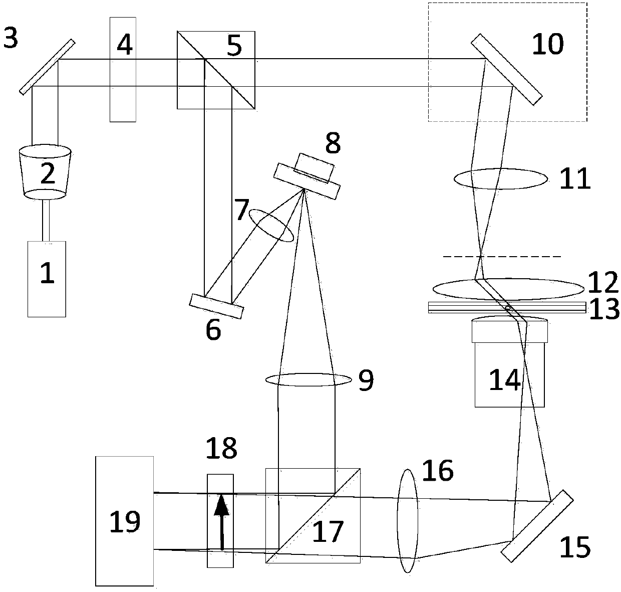
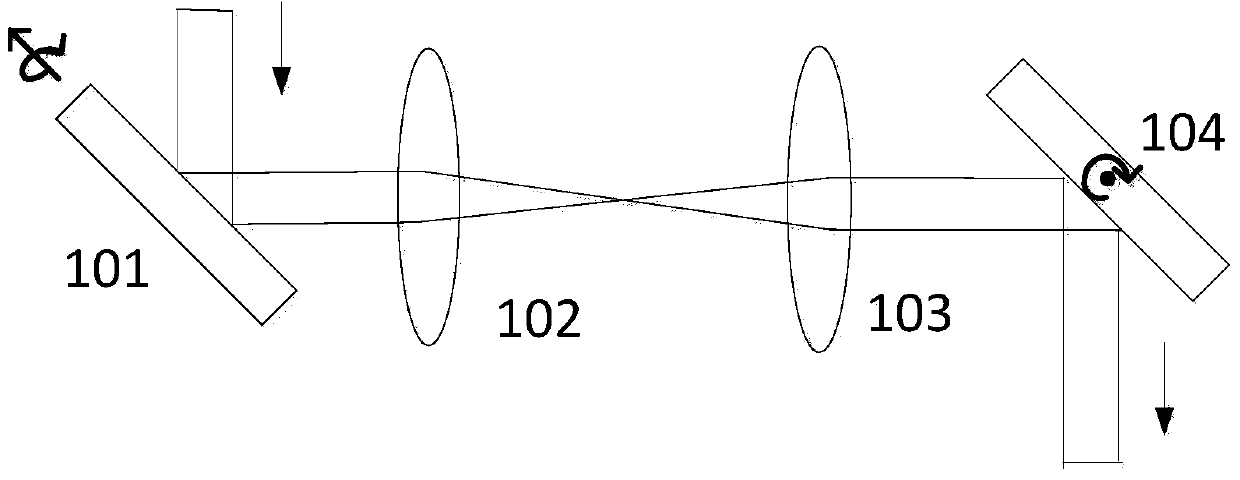
[0045] Such as figure 1 As shown, a high-speed controllable tomographic phase microscopic device includes: a laser 1, a beam expander 2, a mirror 3, a half-wave plate 4, a first polarization beam splitter prism 5, a mirror 6, and a focusing Lens 7, piezoelectric ceramic control mirror 8, collimating lens 9, two-dimensional scanning system 10, scanning lens 11, converging lens 12, sample 13, microscope objective lens 14, mirror 15, microscope field lens 16, second Polarization beam splitter prism 17, polarizer 18, CCD19; As figure 2 As shown, the two-dimensional scanning system 10 is composed of a one-dimensional scanning lens 101 , a lens 102 , a lens 103 and a one-dimensional scanning lens 104 .

[0046] Wherein, the laser 1 emits a laser beam, the beam expands through the beam expander 2 and irradiates on the reflector 3, the laser reflected by the reflector 3 transmits a half-wave plate 4, and irradiates on the first polarizing beam splitter prism 5, By adjusting the ang...


PUM


Abstract

The invention discloses a microscopy device for a controlled high-speed chromatography phase position. The microscopy device comprises a two-dimension scanning system, a first 4f system, a sample, a second 4f system, a piezoelectric ceramic control reflecting mirror, an optical path difference, a second polarization splitting prism, a polarizing film and a CCD (charge coupled device), wherein the two-dimension scanning system, the first 4f system, the sample and the second 4f system are successively arranged along a sample light path; the piezoelectric ceramic control reflecting mirror is arranged on a reference light path, and the optical path difference is used for changing the sample light path and the reference light path; the second polarization splitting prism is used for enabling the sample light and the reference light to become a bundle; the polarizing film and the CCD are successively arranged along an emergent light path of the polarization splitting prism. The invention also discloses a microscopy method of the controlled high-speed chromatography phase position. The microscopy device provided by the invention has the advantages that the system stability is high, the controllability is strong, the economy is good, the complicated angle scanning is realized, and the speed of a chromatography phase position microscopy system is increased by more than 4 times.

Description

technical field [0001] The invention belongs to the field of optical super-resolution microscopy, in particular to a microscopic method and device for controlling high-speed tomographic phase. Background technique [0002] Different cells in biological tissues have different refractive indices and undertake different organizational tasks; the nucleus, cytoplasm and various organelles in the same cell have different refractive indices. When the biological life activities change, the corresponding tissue The distribution of the refractive index of the cells in the cell will also change, such as the increase of the refractive index of cancerous cells, the change of the refractive index distribution of red blood cells infected by Plasmodium, etc. an important subject. [0003] The observation of the refractive index of cells is different from the observation of fluorescent samples and stained samples. The cells are almost in a transparent state, and the modulation of the refrac...

Claims


Application Information

Patent Timeline
Patent Type & Authority Applications(China)
IPC IPC(8): G01N21/41G02B21/00G01N21/01
Inventor 匡翠方修鹏刘旭葛剑虹
Owner ZHEJIANG UNIV
Why Eureka
Try Eureka