
Method and Apparatus for Light Field Generation

Active Publication Date: 2018-07-26
CHARLES STARK DRAPER LABORATORY
View PDF3 Cites 13 Cited by
  • Summary
  • Abstract
  • Description
  • Claims
  • Application Information

AI Technical Summary

Benefits of technology

The present invention provides a radiation projector that uses nanophotonic antennas to generate electromagnetic radiation and a control signal to recurse the phase of the antennas to cause the radiation to span a continuous solid angle. The projector can generate dynamic three-dimensional imagery and can be used in applications such as 3-D display. The invention also includes a MEMS phase shifter for shifting the phase of the illumination patterns and a database containing data representative of the three-dimensional scene scanned from several different directions. The invention also includes a controller for providing phase shift control signals to the antennas and a lens for directing the emitted output radiation in a desired direction. The invention allows for efficient and dynamic beam-steering using nanophotonic antennas and can produce high-quality imaging with reduced latency.

Problems solved by technology

Creating 3-D imagery by projecting an image sequence synchronized to the oscillatory motion of an opto-mechanical beam-steering device, such as the lenticulars described in U.S. Pat. No. 7,864,419, is noisy, difficult to construct at scales greater than 30 cm×30 cm, and have a limited field of view.
Moreover, these devices are difficult to operate in a two-axis (full parallax) scan mode because at least one mechanical axis must run at a very high frequency.
However, the generation of dynamic (video) imagery using the Gerchberg-Saxton algorithm as reported is computationally expensive and requires orders of magnitude more delay-line controllers than the invention described here.
No electro-holographic or diffractive display of practical utility at a variety of scales has yet been demonstrated in the prior art.
One reason for this is that the optical modulator is either too slow, or has pixels that are too large compared to the wavelength of light (resulting in imagery that either restricts head motion or requires a large output lens), or is run in a diffractive mode other than phased-array beam steering, which requires a complex scheme for asserting phase delays.
With rare exception, no autostereoscopic display technology has been of sufficient quality and utility to be widely adopted.
Today's volumetric, lenticular, multi-projector, and scanned-view 3-D displays have been some combination of: unsuitably large for packaging into tablet or television form factors, uncomfortably narrow viewing angle, low image resolution at the display surface and throughout the reconstructed image volume, and computationally intensive.
Systems of this type have suffered from drawbacks including: narrow horizontal and / or vertical field of view, insufficient angular resolution, and acoustically noisy operation.

Method used


Image

  • Method and Apparatus for Light Field Generation
  • Method and Apparatus for Light Field Generation
  • Method and Apparatus for Light Field Generation

Examples


Embodiment Construction

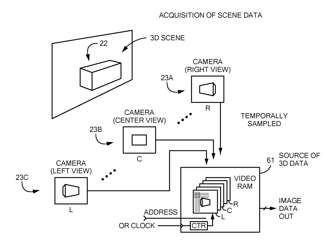
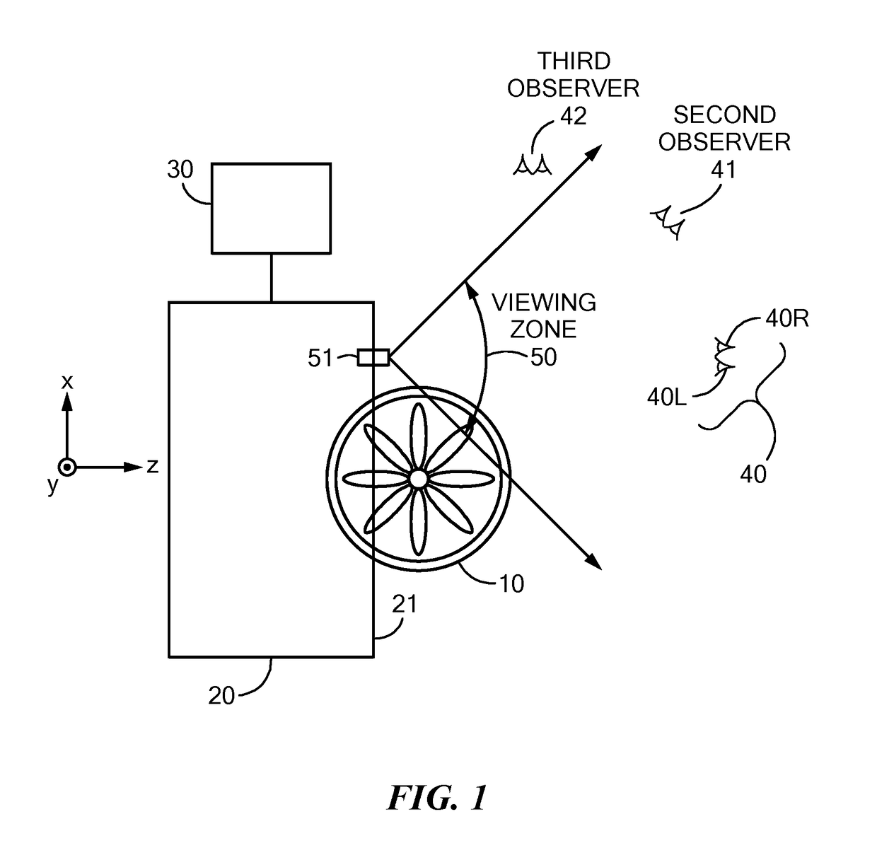
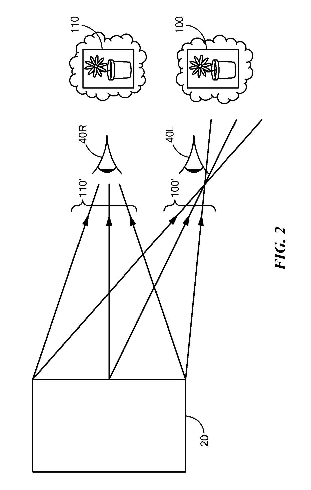
[0021]In accordance with an embodiment of the present invention, a radiation projector is provided that has a plurality of nanophotonic antennas configured to emit electromagnetic radiation. The radiation projector also has phase delay elements, each one characterized, at any particular moment, by a phase delay. At least one phase delay element is associated with at least one of the plurality of nanophotonic antennas. The radiation projector also has a control signal generator configured to generate a control signal associated with the plurality of delay elements, wherein the control signal is further configured to recurrently update phase delays of the plurality of phase delay elements in such a manner as to cause the electromagnetic radiation to substantially span at least one contiguous solid angle. In certain embodiments of the invention output of the antennas may generate a three dimensional light field of imagery.

[0022]A nanophotonic phased array can be configured to generate ...


PUM


Abstract

A nanophotonic phased array is configured to generate dynamic three-dimensional imagery when employed as an oscillatory beam-steering device. A scanning nanophotonic phased array generates programmable light fields. That is, a phased array generates reconfigurable light fields when controlled to perform an angular scan of incident illumination synchronized with respect to modulation of the incident illumination.

Description

[0001]The present application claims the benefit of U.S. Provisional Patent Application No. 62 / 450,855, filed Jan. 26, 2017, titled “Method and Apparatus for Light Field Generation,” the entire contents of which are hereby incorporated by reference, for all purposes.TECHNICAL FIELD[0002]The present invention relates to the use of an optical array of antennas, and more particularly to nanophotonic antennas in a phased array associated with a phase shifter, as a light field generator for such uses that include 3-D display and beam scanning for electronic display among others.BACKGROUND ART[0003]Autostereoscopic 3-D displays generate imagery visible to the unaided eye. The specific characteristics of the imagery depend on the operational mechanisms of the display device, but their properties usually include: (1) appearance in front of, behind, or straddling the display, (2) visibility as three-dimensional within a range of angles or distances from the display, (3) having a perceived sp...

Claims


Application Information

Patent Timeline
IPC IPC(8): G03H1/04
CPCH04N13/32G03H2001/0088G03H1/0443H04N13/305G02F1/2955G02F2202/36
Inventor FAVALORA, GREGG E.SPECTOR, STEVEN J.LANE, BENJAMIN F.
Owner CHARLES STARK DRAPER LABORATORY
Learn More