Optical scanning-type touch panel

a touch panel and optical scanning technology, applied in the field of optical scanning type touch panel, can solve problems such as impaired s/n ratio, and achieve the effect of improving the light receiving signal level

Inactive Publication Date: 2009-04-21
FUJITSU LTD
View PDF18 Cites 13 Cited by
  • Summary
  • Abstract
  • Description
  • Claims
  • Application Information

AI Technical Summary

Benefits of technology

[0015]An optical scanning-type touch panel of the seventh invention comprising: a light retro-reflector provided outside of a predetermined region; an optical scanning unit for angularly scanning light in a plane substantially parallel to the predetermined region; and a light receiving unit for receiving reflected light of scanning light of the optical scanning unit from the light retro-reflector, for detecting a scanning light cut-off position, which is produced in the predetermined region by an indicator, based on a light receiving output of the light receiving unit that corresponds to a scanning angle, wherein the optical scanning unit is provided with a protective film having a maximum reflectance at an angle of incidence corresponding to a scanning angle at which the quantity of the reflected light is minimum. In the optical scanning-type touch panel of the seventh invention, the optical scanning unit is provided with the protective film having the maximum reflectance at an angle of incidence corresponding to a scanning angle at which the quantity of the reflected light is minimum so as to improve the light receiving signal level in scanning the position at which the quantity of the reflected light is minimum with light.

Problems solved by technology

As a result, the S / N ratio is impaired, causing a malfunction.

Method used


Image

  • Optical scanning-type touch panel
  • Optical scanning-type touch panel
  • Optical scanning-type touch panel

Examples


Embodiment Construction

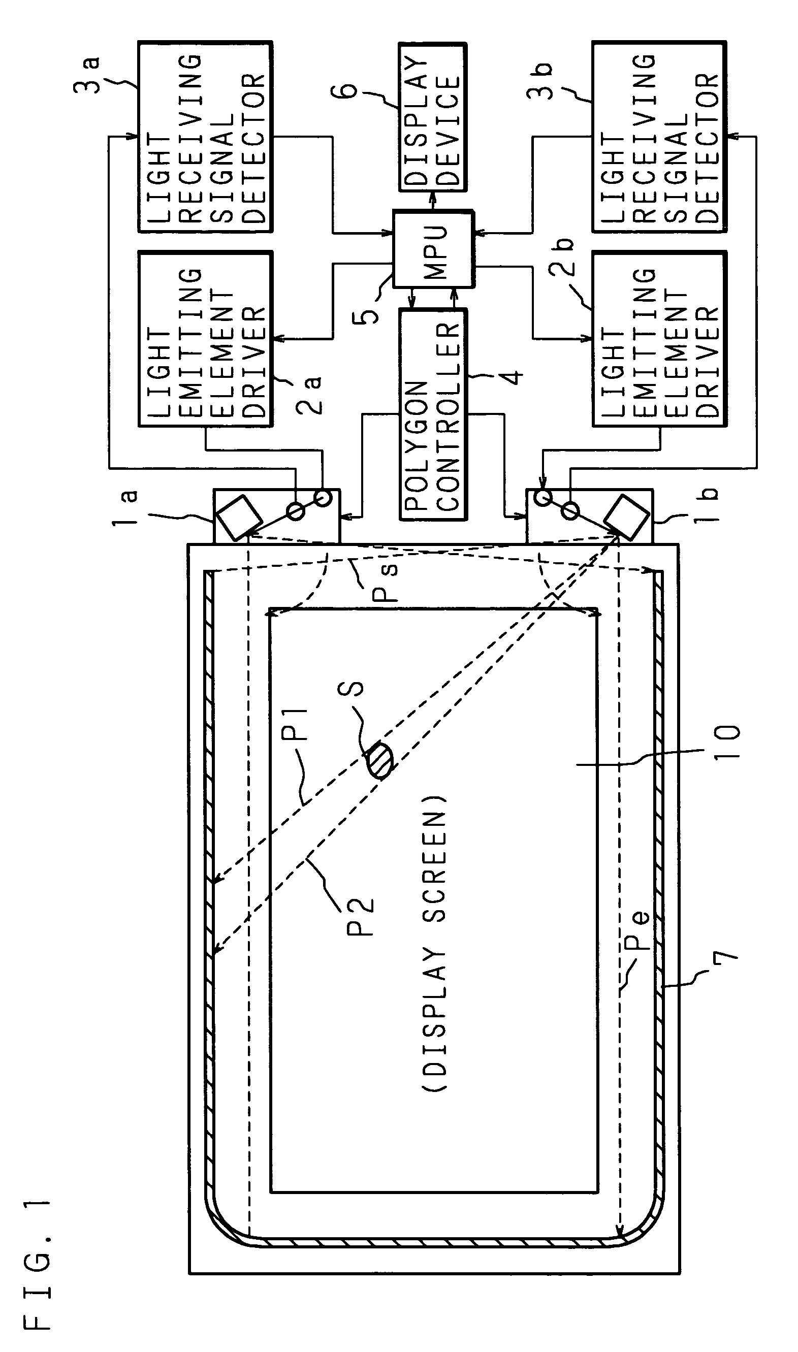
[0037]The following description will explain the present invention in detail with reference to the drawings illustrating an embodiment thereof. FIG. 1 is a schematic diagram showing the basic structure of an optical scanning-type touch panel of the present invention.

[0038]In FIG. 1, reference numeral 10 is a rectangular display screen of a CRT, flat display panel (PDP, LCD, EL, etc.) or projection-type image display device of electronic equipment such as a personal computer, and the optical scanning-type touch panel is constructed as the display screen of a PDP (Plasma Display Panel) in this embodiment.

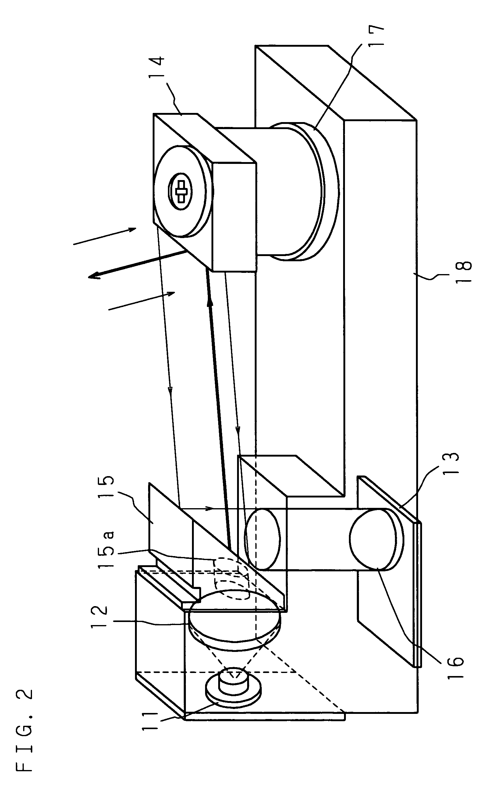
[0039]Optical units 1a and 1b having therein an optical system composed of a light emitting element, a light receiving element, a polygon mirror and various lenses are respectively provided on the outside of both corners of one short side (the right side in this embodiment) of this rectangular display screen 10 that is the extent of a plane specified as a target area to be touched by ...


PUM


Abstract

Laser light emitted by a light emitting element is made parallel light by a collimation lens, passes through an aperture of an aperture mirror, and is then angularly scanned in a plane substantially parallel to a display screen by rotation of a polygon mirror and projected onto a recurrence reflection sheet. Then, after the reflected light from the recurrence reflection sheet is reflected by the polygon mirror and aperture mirror, the light is focused by a condenser lens to enter a light receiving element. The aperture mirror has an asymmetrical shape in the scanning direction and/or the vertical direction about the optical axis, according to a scanning surface opening width of the polygon mirror.

Description

[0001]This application is a continuation of international application PCT / JP99 / 06809 filed Dec. 3, 1999.TECHNICAL FIELD[0002]The present invention relates to an optical scanning-type touch panel for optically detecting the position of an indicator on a display screen.BACKGROUND ART[0003]With the spread of computer systems, mainly personal computers, there has been used a device for inputting new information or giving various instructions to a computer system by pointing at a position on a display screen of a display device on which information is displayed by the computer system, with a person's finger or a specific indicator.[0004]In order to perform an input operation with respect to the information displayed on the display screen of the display device of a personal computer or the like by a touching method, it is necessary to detect a touched position (indicated position) on the display screen with high accuracy. As one example of such a method of detecting the indicated position...

Claims


Application Information

Patent Timeline
Patent Type & Authority Patents(United States)
IPC IPC(8): G06F3/042G06F3/041
CPCG06F3/0423
Inventor SANO, SATOSHIIWAMOTO, YASUHIDENAKAZAWA, FUMIHIKOYAMAGUCHI, NOBUYASU
Owner FUJITSU LTD
Why Eureka
Try Eureka