Vibrating Mirror Element

a mirror element and mirror technology, applied in the field of mirror elements, can solve the problems of disadvantageous deformation of the first spring portion, inclination and vibration of the reflecting mirror portion, and may conceivably be so reduced, so as to prevent application, facilitate deformation, and facilitate further expansion of the vibration of the mirror portion

Inactive Publication Date: 2010-06-10
FUNAI ELECTRIC CO LTD
View PDF9 Cites 6 Cited by
  • Summary
  • Abstract
  • Description
  • Claims
  • Application Information

AI Technical Summary

Benefits of technology

[0029]In this case, the vibrating mirror element preferably further includes a pair of fixed portions provided on sides opposite to connecting portions between end portions of the second beam portions and the pair of driving portions and in the vicinity of central portions of the pair of driving portions in the longitudinal direction respectively for constituting fixed ends in vibration of the pair of driving portions and fixing the pair of driving portions, and the pair of recess portions are preferably provided in the vicinity of the central portions of the pair of driving portions in the longitudinal direction on the sides of the connecting portions respectively. According to this structure, the pair of recess portions are positioned in the vicinity of the pair of fixed portions constituting the fixed ends of the pair of driving portions respectively, whereby the pair of driving portions can be inhibited from deformation on the positions of the pair of recess portions. Thus, the pair of recess portions which are narrow portions included in the pair of driving portions can be prevented from application of stress.
[0030]In the aforementioned vibrating mirror element provided with the recess portions, the widths of portions of the driving portions other than the recess portions are preferably rendered substantially identical to each other along the longitudinal direction of the driving portions. According to this structure, the driving portions can be rendered easily substantially uniformly deformable along the longitudinal direction, whereby vibration of the mirror portion can be easily controlled.
[0031]In the vibrating mirror element according to the aforementioned aspect, the width of the pair of first beam portions and the width of the pair of second beam portions are preferably rendered not more than half the width of the pair of driving portions. According to this structure, the pair of first beam portions and the pair of second beam portions can be more easily deformed, whereby vibration of the mirror portion can be further enlarged.

Problems solved by technology

In the vibrator (vibrating mirror element) described in the aforementioned Japanese Patent No. 3956933, however, the width of the first spring portions is rendered larger than that of the second spring portions receiving the driving sources on the upper portions thereof, and hence the first spring portions are disadvantageously hard to deform.
When flexural vibration of the second spring portions is converted to torsional vibration of the first spring portions, therefore, torsional vibration of the first spring portions may conceivably be so reduced that inclination and vibration of the reflecting mirror portion are disadvantageously reduced.
Further, the driving sources arranged on the upper portions of the second spring portions are formed to extend oppositely to the first spring portions and the reflecting mirror portion, and hence a region occupied by the driving sources, the first spring portions and the reflecting mirror portion is disadvantageously elongated in the extensional direction of the driving sources in plan view.
When the vibrator is assembled into an apparatus, therefore, the elongated region may conceivably so restrict the design of the apparatus that it is difficult to downsize the apparatus.
Further, a structure for electrically connecting the driving sources with an external device is disadvantageously complicated due to the provision of the four driving sources made of the piezoelectric substance.
The optical scanning apparatus described in the aforementioned Japanese Patent Laying-Open No. 2007-312465 is formed not to twist the support portions, and hence inclination and vibration of the mirror may conceivably be disadvantageously reduced due to suppression of resonance on the support portions.
Further, the piezoelectric elements are provided on the four sides of the movable frame respectively, and hence a structure for electrically connecting the piezoelectric elements with an external device is disadvantageously complicated.
In the driving mirror described in the aforementioned Japanese Patent Laying-Open No. 2007-10823, the width of the beams is conceivably rendered substantially identical to that of the four arms provided with the piezoelectric films, and hence the beams may conceivably be disadvantageously hard to deform.
In each of the scanning apparatus and the scanning mirror described in the aforementioned Japanese Patent No. 3767577 and the aforementioned Japanese Patent Laying-Open No. 2004-361889, the piezoelectric element (piezoelectric members) is directly provided on the elastic body (cantilevers), and hence the elastic body (cantilevers) may conceivably be disadvantageously hard to resonate.
Therefore, it may conceivably be disadvantageously difficult to enlarge vibration of the polariscope (rotating mirror) due to the difficulty in resonance of the elastic body (cantilevers).
In the optical scanning apparatus described in the aforementioned Japanese Patent Laying-Open No. 2006-293116, the overall substrate must be vibrated, and hence it may conceivably be disadvantageously difficult to enlarge vibration of the mirror portion.
The two-dimensional optical scanner described in the aforementioned Japanese Patent No. 4092283 includes the four piezoelectric unimorphic diaphragms, and hence a structure for electrically connecting the piezoelectric unimorphic diaphragms with an external device is disadvantageously complicated.

Method used


Image

  • Vibrating Mirror Element
  • Vibrating Mirror Element
  • Vibrating Mirror Element

Examples


Embodiment Construction

[0054]An embodiment of the present invention is now described with reference to the drawings.

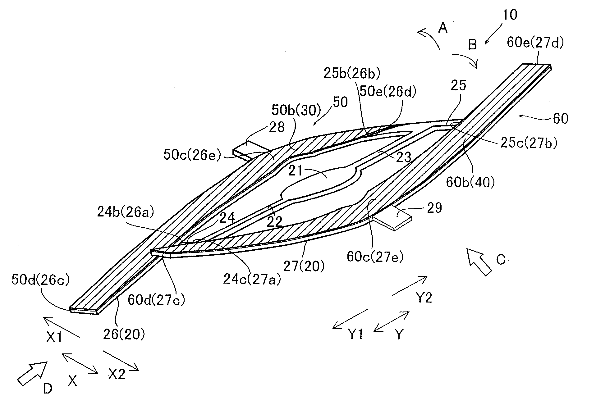
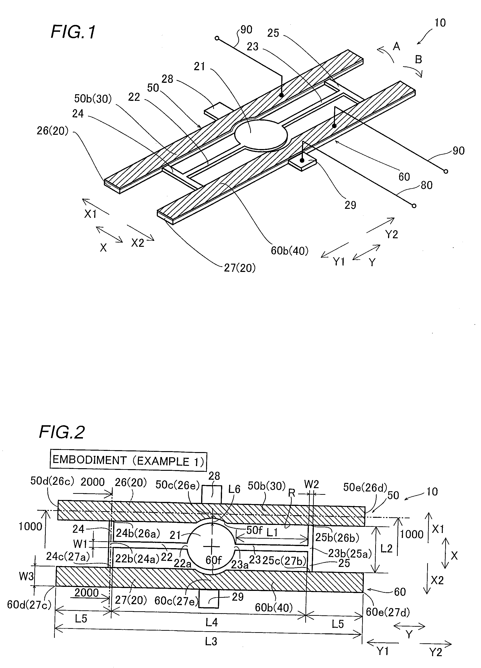
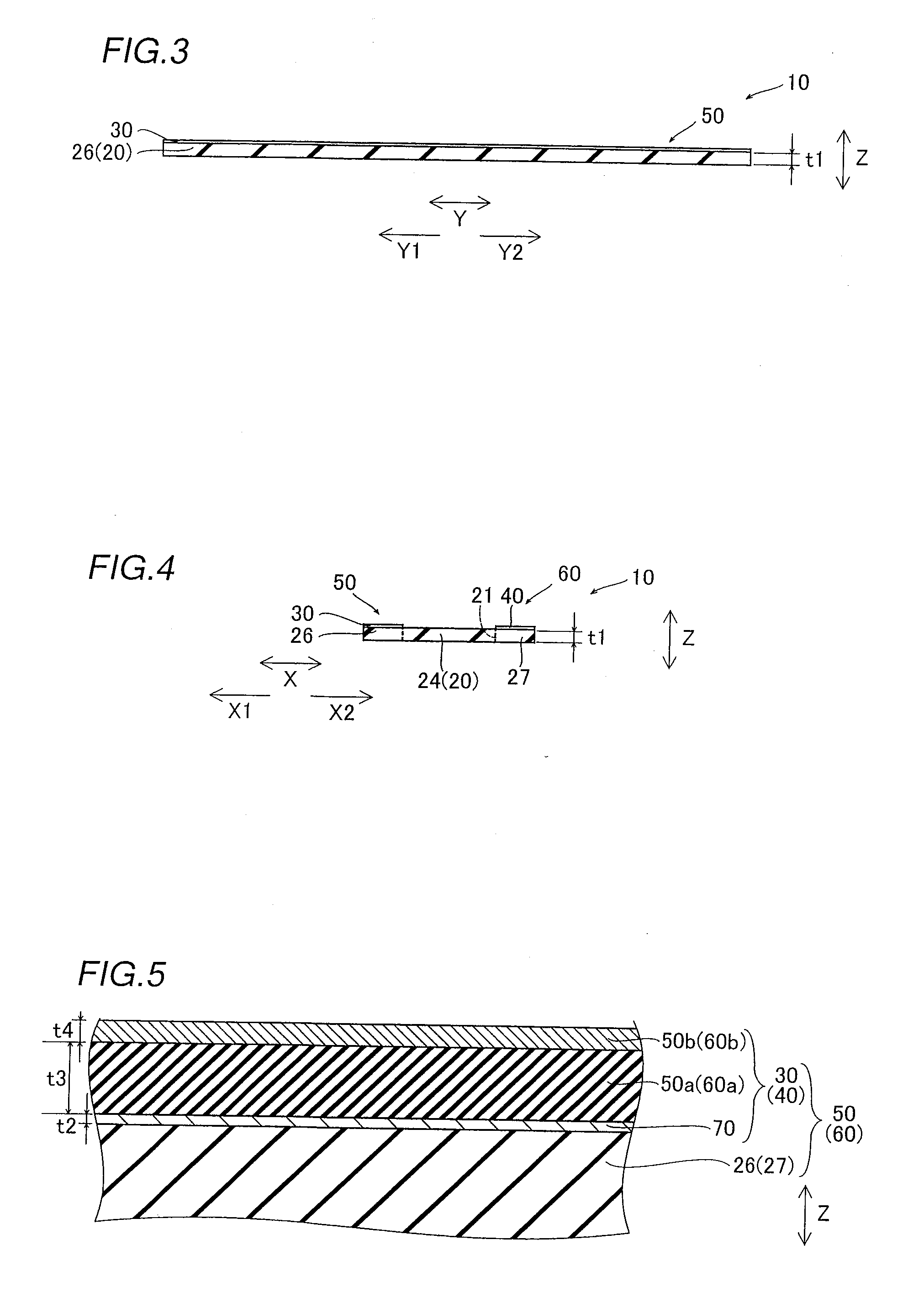
[0055]First, the structure of a vibrating mirror element 10 according to the embodiment of the present invention is described with reference to FIGS. 1 to 5.

[0056]The vibrating mirror element 10 according to the embodiment of the present invention is constituted of a substrate 20 and piezoelectric elements 30 and 40 arranged on the substrate 20, as shown in FIGS. 1 and 2. The substrate 20 includes a mirror portion 21 reflecting light, torsion bars 22 and 23 having identical shapes, bars 24 and 25 having identical shapes, a movable portion 26 formed on the side of a direction X1, and another movable portion 27, having a shape identical to that of the movable portion 26, formed on the side of a direction X2. The torsion bar 22 and the bar 24 are formed on the side of the mirror portion 21 in a direction Y1, while the torsion bar 23 and the bar 25 are formed on the side of the mirror portion 21...


PUM


Abstract

This vibrating mirror element includes a pair of first beam portions supporting a mirror portion in a vibratile manner, a pair of second beam portions connected with the pair of first beam portions respectively, and a pair of driving portions connected with the pair of second beam portions respectively. The mirror portion is arranged in a region surrounded by the pair of second beam portions and the pair of driving portions. The width of the pair of first beam portions and the width of the pair of second beam portions are rendered smaller than the width of the pair of driving portions.

Description

BACKGROUND OF THE INVENTION[0001]1. Field of the Invention[0002]The present invention relates to a vibrating mirror element, and more particularly, it relates to a vibrating mirror element including driving portions.[0003]2. Description of the Background Art[0004]A vibrating mirror element including driving portions is known in general, as disclosed in each of Japanese Patent No. 3956933, Japanese Patent Laying-Open Nos. 2007-312465 and 2007-10823, Japanese Patent No. 3767577, Japanese Patent Laying-Open Nos. 2004-361889 and 2006-293116 and Japanese Patent No. 4092283, for example.[0005]The aforementioned Japanese Patent No. 3956933 discloses a vibrator (vibrating mirror element) including a reflecting mirror portion, a pair of first spring portions having first end portions connected to both sides of the reflecting mirror portion respectively for supporting the reflecting mirror portion in a vibratile manner, a pair of second spring portions connected to second end portions of the ...

Claims


Application Information

Patent Timeline
Patent Type & Authority Applications(United States)
IPC IPC(8): G02B26/08
CPCG02B26/0841
Inventor KANNO, ISAKUMURAYAMA, MANABUFUJII, HITOSHI
Owner FUNAI ELECTRIC CO LTD
Why Eureka
Try Eureka