

System and method for obtaining optical signal information
- Summary
- Abstract
- Description
- Claims
- Application Information
AI Technical Summary
Problems solved by technology
Method used
Image

Examples
Embodiment Construction
[0006]The preferred embodiments according to the present invention now will be described more fully hereinafter with reference to the accompanying drawings, in which some, but not all embodiments of the inventions are shown. Indeed, these inventions may be embodied in many different forms and should not be construed as limited to the embodiments set forth herein; rather, these embodiments are provided so that this disclosure will satisfy applicable legal requirements. Like numbers refer to like elements throughout.
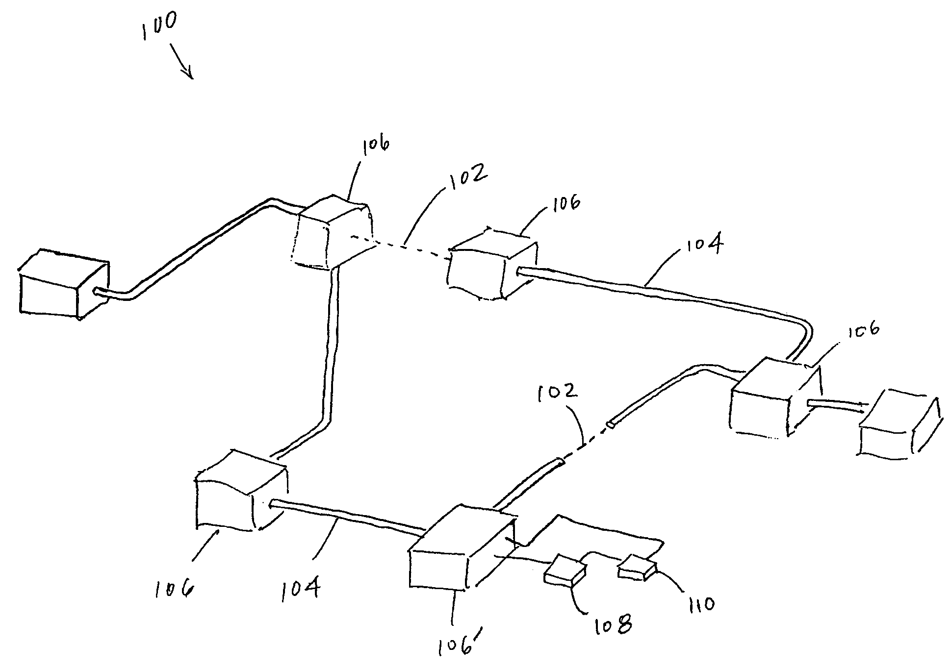
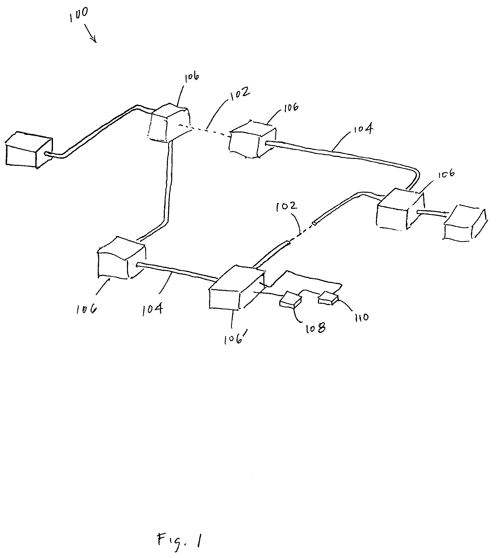
[0007]Referring to FIG. 1, therein is shown a portion of an optical network 100, the illustrated portion being configured in accordance with an embodiment of the present invention. The network portion 100 includes multiple optical paths, such as free-space areas 102 for propagation of optical or electromagnetic waves and discrete waveguides 104, such as optical fibers. Both the free-space links 102 and the wave guides 104 are capable of supporting the propagation of signal...
PUM
 Abstract
Description
Claims
Application Information