
Belt unit for continuously variable transmission

a technology of continuous variable transmission and belt unit, which is applied in the direction of driving belt, belt/chain/gearing, driving belt, etc., can solve the problems of variable friction loss, loss generation, and other losses

Inactive Publication Date: 2010-06-10
HYUNDAI MOTOR CO LTD
View PDF4 Cites 3 Cited by
  • Summary
  • Abstract
  • Description
  • Claims
  • Application Information

AI Technical Summary

Problems solved by technology

The belt is a main component for transmitting power in a CVT and various friction losses occur due to relative motions between the components of the CVT.
For example, the friction loss is generated between a segment and the pulley surface as well as between a segment and a band, and a band and a band, and other losses are generated.
However, about 65 to 75% of the friction loss generated in a CVT is a loss due to band friction, which is a friction loss due to relative motion between a segment and a band and normal force exerted in a segment shoulder where the band is in close contact by pulley compression force.
But, since only the linear velocity difference between the band and the segment is considered to reduce the relative velocity difference, there is a limit in improving performance for reducing the relative velocity difference.

Method used


Image

  • Belt unit for continuously variable transmission
  • Belt unit for continuously variable transmission
  • Belt unit for continuously variable transmission

Examples


Embodiment Construction

[0027]Reference will now be made in detail to various embodiments of the present invention(s), examples of which are illustrated in the accompanying drawings and described below. While the invention(s) will be described in conjunction with exemplary embodiments, it will be understood that present description is not intended to limit the invention(s) to those exemplary embodiments. On the contrary, the invention(s) is / are intended to cover not only the exemplary embodiments, but also various alternatives, modifications, equivalents and other embodiments, which may be included within the spirit and scope of the invention as defined by the appended claims.

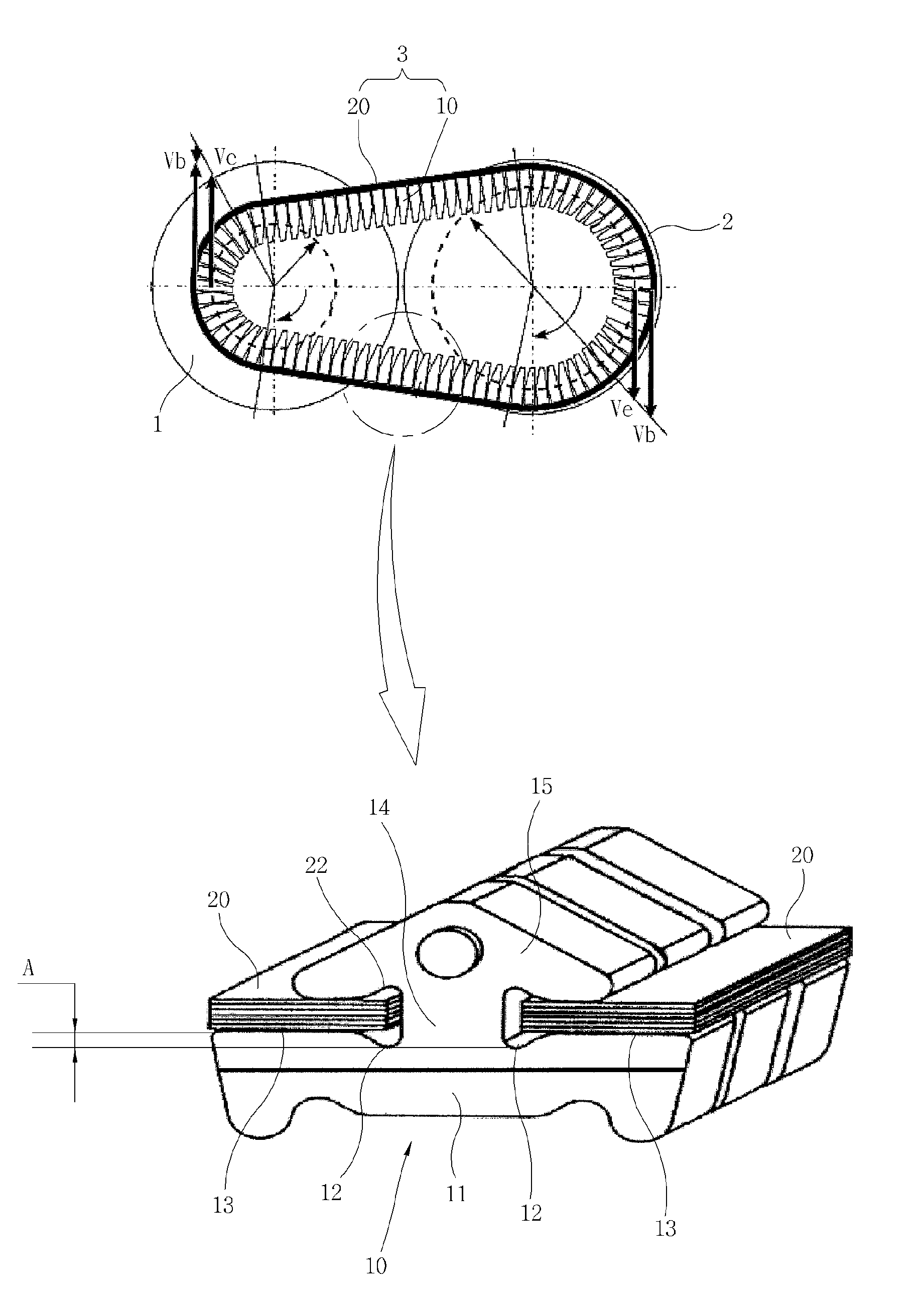
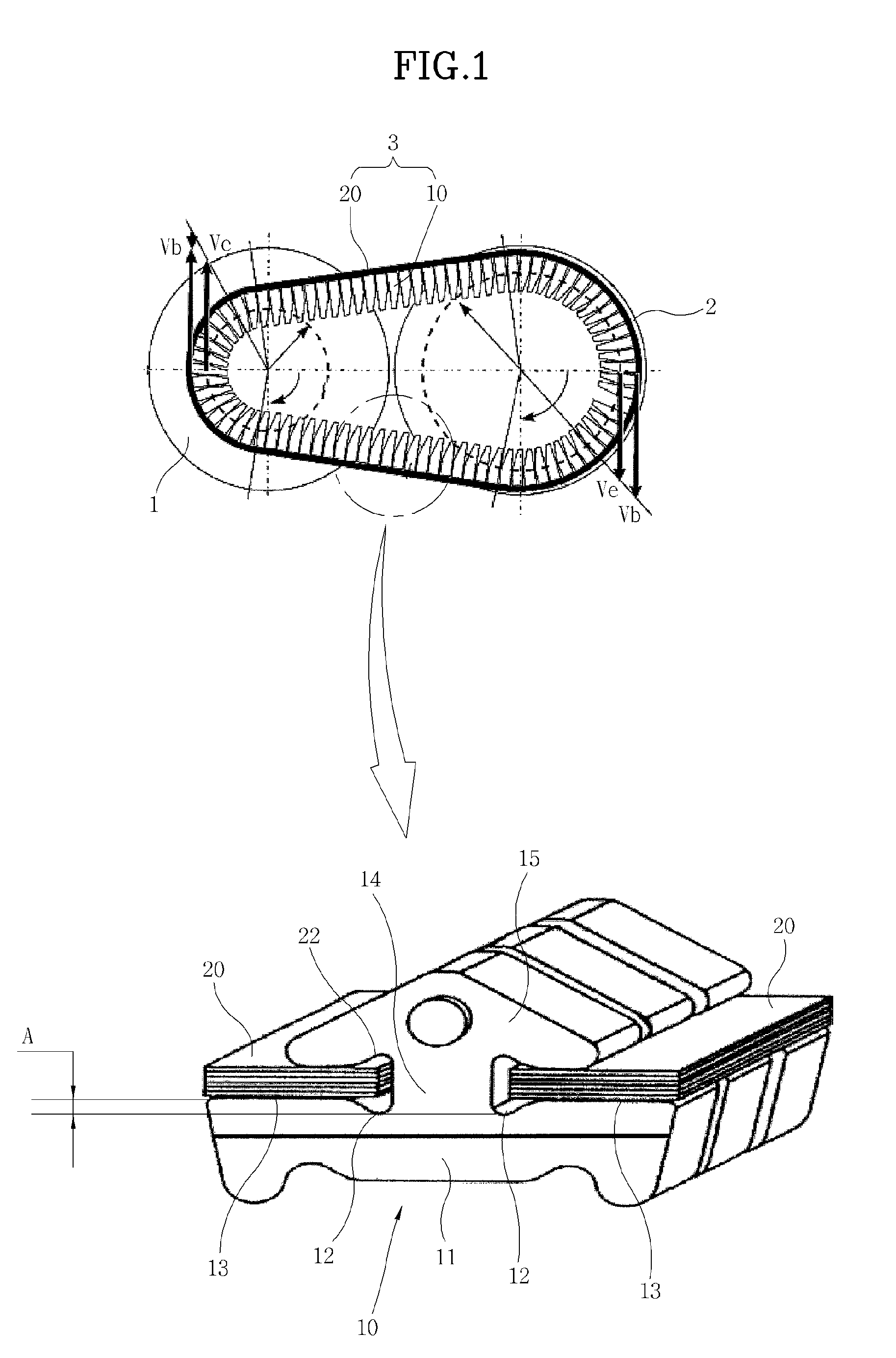
[0028]FIG. 1 is a diagram illustrating the configuration of a belt unit for a continuously variable transmission according to an exemplary embodiment of the present invention. A CVT (Continuously Variable Transmission) of the present invention includes a primary pulley connected with a power shaft, a secondary pulley connected with a ...


PUM


Abstract

A belt unit for a continuously variable transmission that transmits power from a primary pulley to a secondary pulley, may include at least a band overlapped each other, and a segment including a body base and a locking end portion which are connected by a neck therebetween, wherein an upper surface of the at least a band is coupled to the locking end portion and a lower surface of the at least a band is coupled to a segment shoulder of the body base, and wherein lower grooves are formed at lower portions of the neck between the neck and the segment shoulder of the body base at both sides of the neck such that an upper surface of the respective body base is higher than the corresponding lower groove to form a contact radius difference between the lower groove and the upper surface of the body base.

Description

CROSS-REFERENCE TO RELATED APPLICATIONS[0001]The present application claims priority to Korean Application Serial Number 10-2008-0122664, filed on Dec. 4, 2008, the entire contents of which are incorporated herein for all purposes by this reference.BACKGROUND OF THE INVENTION[0002]1. Field of the Invention[0003]The present invention relates to a continuously variable transmission, particularly a belt unit for a continuously variable transmission that removes a relative velocity difference that causes slip under an OD (Over Drive, 2000 rpm) condition which is most used in practical traveling conditions of a vehicle.[0004]2. Description of Related Art[0005]In general, CVTs (Continuously Variable Transmission) is devices that transmit power using a belt connecting a primary pulley with a secondary pulley, in which the primary pulley is connected with a power shaft and the secondary pulley is connected with a driven shaft.[0006]For this purpose, the belt is composed of segments and band...

Claims


Application Information

Patent Timeline
Patent Type & Authority Applications(United States)
IPC IPC(8): F16G1/22
CPCF16G5/16F16H9/24
Inventor LEE, JUHYEONGLEE, JAEHYUN
Owner HYUNDAI MOTOR CO LTD
Learn More