
Skinning Knife

a technology of skinning knife and blade, which is applied in the field of skinning knives, can solve the problems of awkward use of devices and too easy use, and achieve the effect of improving safety

Inactive Publication Date: 2010-06-17
JAMISON JOHN RICHARD
View PDF14 Cites 5 Cited by
  • Summary
  • Abstract
  • Description
  • Claims
  • Application Information

AI Technical Summary

Benefits of technology

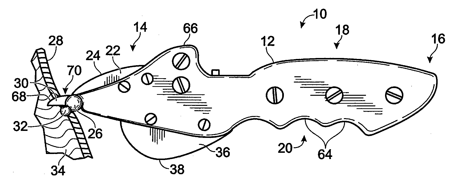
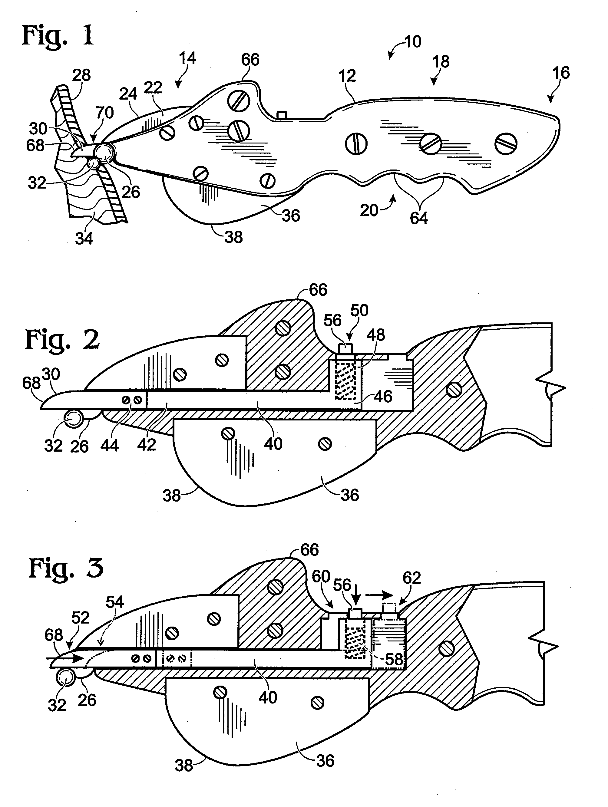
[0012]The invention may also provide a second spreading member disposed below and forward of the first spreading member, the second spreading member also having a three-dimensional forwardly convex surface, or the two convex surfaces may be provided by a single spreading member. The invention may also be further provided with a downwardly directed convex skinning blade for separating the hide of an animal from the meat. In its simplest embodiment, the invention may comprise a handle, a fixed blade, and a fixedly attached spreading member, used in a forwardly-directed motion to skin the animal, the relative sizes of the parts being adapted to the size and thickness of the animal hide. In each of the embodiments, the use of a fixedly attached, convex spreading member allows the skinning knife to be wielded in a forward motion, away from the user, thus improving its safety over tools that include sharp components and that are used with a pulling motion.

Problems solved by technology

Skinning involves removing the hide of the animal from the musculature, or meat, of the animal with minimal damage to either the meat or the hide (or to the fur, if applicable), which is a challenging task.
However, this device can be awkward to use because of the wide-swinging arm and the spreading member includes fairly narrow walls that concentrate force on the meat.
However, this too may be awkward to use because the spreading member and strap hang loosely when the spreading member is not attached to the tip and, when the spreading member is attached to the tip, the spreading member covers a portion of the blade that is most useful in slitting the hide.

Method used


Image

  • Skinning Knife
  • Skinning Knife
  • Skinning Knife

Examples


embodiment 110

[0044]In use of alternative skinning knife embodiment 110, the spreading members are initially retracted so that the tip 132 of the multi-purpose blade 112 can be used to punch a hole in the animal hide. Then, the spreading members 126 and 128 are moved to their forward most position so that, as multi-purpose blade 112 is used to slit the hide, the two separated parts of the hide are spread. Finally, when a sufficiently long slit has been made in the hide, the spreading members are again retracted and the multi-purpose blade 112 is used to separate the hide from the meat.

[0045]Referring now to FIGS. 8-10, a second alternative embodiment of a skinning knife 150 is shown that is a variant of alternative skinning knife 110. Like skinning knife 110, skinning knife 150 features a multi-purpose blade 112 having a beveled cutting edge 114, and a two-part handle 116 attached on either side to blade 112 by two screws 124. However, skinning knife 150 further provides a two-part blade sheath 1...

embodiment 150

[0046]The mechanism that actuates movement of blade sheath 152 and triangular spreading member 154 in skinning knife embodiment 150 is now described with reference to an enlarged side elevation shown in FIG. 10. Depressing a sheath thumb tab 156 compresses a flat spring 157 preferably having overlapping leaves, which unlocks a spring pin 164 from its forward latched position 165 so that it may travel fore and aft within a channel 166 cut into, and accessible from, a lower surface of the tang of blade 112, behind cutting edge 114. The surface of sheath thumb tab 156 may be fashioned with a thumb grip, preferably having a roughened, sticky, or otherwise high-friction surface, to prevent slipping. A second pin 168, located adjacent to triangular spreading member 154, travels in tandem, within a second channel 170, which is accessible from a top surface of blade 112. When spring pin 164 reaches the rearmost extent of its travel, pin 164 drops into a rearward latched position 172 until s...

embodiment 210

[0051]FIG. 18 presents an add-on spreading member 227 that may be used to convert a conventional knife blade 228 into a skinning knife resembling fixed blade embodiment 210. Spreading member 227 comprises a generally convex, closed object, into which a slit 230 may be cut for receiving a sharp tip of knife blade 228. Spreading member 227 may be hollow or solid. In a preferred embodiment, spreading member 229 is spherical; however, in general, consistent with previous embodiments, spreading member 227 may be of any shape that presents a forwardly convex surface in the direction of the tip of knife blade 228. An optional set screw 232 may be mounted orthogonally to the slit 230 through a set screw hole 234 for securing spreading member 226 to knife blade 228 as the set screw is tightened and comes into contact with the surface of knife blade 228. Add-on spreading member 227 is preferably made of one or more materials such as metal, plastic, glass, mineral, or crystalline material, or ...


PUM


Abstract

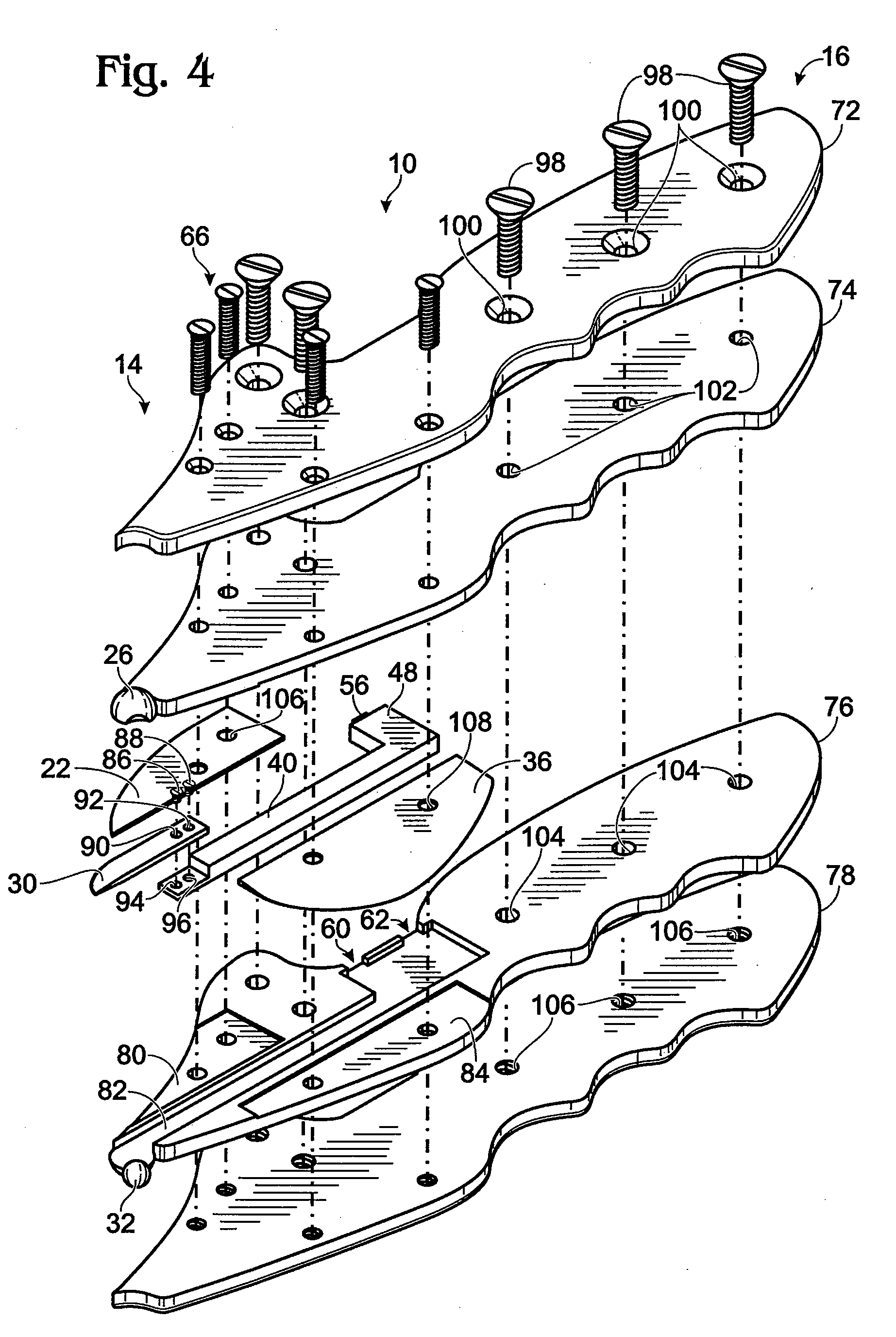
A skinning knife comprising a handle, a convex skinning blade, and one or more spreading members disposed at the forward most position of the knife so as to spread apart two portions of an animal hide that have been separated as the knife is thrust forwardly. A preferred embodiment also features a slitting blade disposed at a forward portion of the handle and having an upwardly- and forwardly-directed cutting edge, and a retractable punch blade disposed in the handle beneath the slitting blade for opening a hole in the hide when the knife is thrust forwardly, the first spreading member having a slot therein for receiving the punch blade. A blade actuation mechanism is provided for selectively moving the punch blade forwardly and rearwardly through the slot in the first spreading member. In alternative embodiments, an actuation mechanism moves the skinning blade or the spreading member.

Description

[0001]This application is a continuation-in-part of U.S. patent application Ser. No. 12 / 142,699, filed on Jun. 19, 2008.BACKGROUND OF THE INVENTION[0002]1. Field of the Invention[0003]This invention relates generally to knives for removing a first, covering material from a second, underlying material and particularly to knives for removing the hide from the musculature of a dead animal.[0004]2. Description of the Related Art[0005]Once an animal has been killed in a hunt it is ordinarily necessary to field dress and skin the animal. Skinning involves removing the hide of the animal from the musculature, or meat, of the animal with minimal damage to either the meat or the hide (or to the fur, if applicable), which is a challenging task.[0006]Various tools have been devised to assist a hunter in skinning an animal that has been killed in hunting. Generally, the idea is to slit the hide and lift it from the meat without damaging the meat. One such tool is shown in Montgomery U.S. Pat. N...

Claims


Application Information

Patent Timeline
Patent Type & Authority Applications(United States)
IPC IPC(8): A22B5/16B26B1/08B26B1/02
CPCA22B5/168B26B3/08B26B3/04
Inventor JAMISON, JOHN RICHARD
Owner JAMISON JOHN RICHARD
Learn More