Parabolic solar energy collector apparatus

a solar energy collector and parabolic technology, applied in the field of solar energy collectors, can solve the problems of limited applicability, physical expansion, and the collectors on the flat plate do not focus the sun's radiation, and achieve the effect of straightforward transportation and assembly

Active Publication Date: 2010-06-17
D & D MFG
View PDF33 Cites 2 Cited by
  • Summary
  • Abstract
  • Description
  • Claims
  • Application Information

AI Technical Summary

Benefits of technology

[0011]In view of the foregoing background, it is therefore an object of the present invention to provide a solar energy collector apparatus that is relatively straightforward to transport and assemble.
[0012]This and other objects, advantages and features in accordance with the present invention are provided by a solar energy collector apparatus comprising a solar collector panel having a parabolic shape, and a base comprising a pair of spaced apart support frames. Each support frame has a parabolic shape corresponding to the parabolic shape of the solar collector panel. Spaced apart rollers may be positioned along an upper surface of each support frame to support the solar collector panel. A drive mechanism may be coupled to the solar collector panel for rotation thereof. The solar collector panel may include a pair of spaced apart guide channels on an underside thereof for contacting the spaced apart rollers to insure that the solar collector panel rotates squarely with respect to the base.
[0013]In accordance with the present invention, the solar energy collector apparatus is relatively straightforward to transport and assemble. These advantages are provided without sacrificing the rigidity or structural integrity of the solar energy collector apparatus incorporating a solar collector panel having a parabolic shape.
[0014]Each support frame may comprise a center section, and spaced apart forward and rear upper sections rotatably coupled to the center section. The forward upper section of each support frame may be rotatable between an up position and a down position so as to not block sunlight based on position of the solar collector panel. Likewise, the rear upper section of each support frame may be rotatable between an up position and a down position so as to not block sunlight based on position of the solar collector panel. Rotation of the forward and rear upper sections between the up and down positions based on the position of the solar collect panel advantageously prevents sun blockage thereon.
[0016]The spaced apart support frames may be symmetrical. Each support frame may comprise a ribbed inner surface and a ribbed outer surface. The ribbed inner and outer surfaces may be symmetrical to one another. Each support frame may be formed as a monolithic unit. Each support frame may comprise at least one of a thermoplastic material and a thermosetting material. These features advantageously allow the solar energy collector apparatus to be light-weight without sacrificing rigidity or structural integrity. These features also help to reduce costs.

Problems solved by technology

Flat plate collectors do not focus the sun's radiation and have limited applicability.
As solar energy collector apparatuses incorporating parabolic type collectors are used to satisfy larger energy requirements, they become physically larger.

Method used


Image

  • Parabolic solar energy collector apparatus
  • Parabolic solar energy collector apparatus
  • Parabolic solar energy collector apparatus

Examples


Embodiment Construction

[0025]The present invention will now be described more fully hereinafter with reference to the accompanying drawings, in which preferred embodiments of the invention are shown. This invention may, however, be embodied in many different forms and should not be construed as limited to the embodiments set forth herein. Rather, these embodiments are provided so that this disclosure will be thorough and complete, and will fully convey the scope of the invention to those skilled in the art. Like numbers refer to like elements throughout.

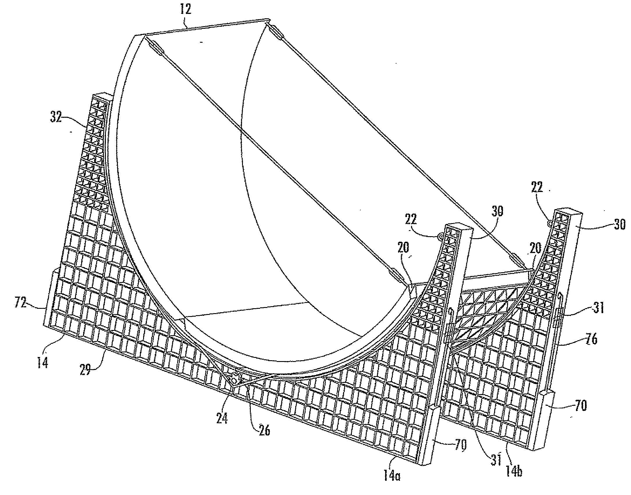
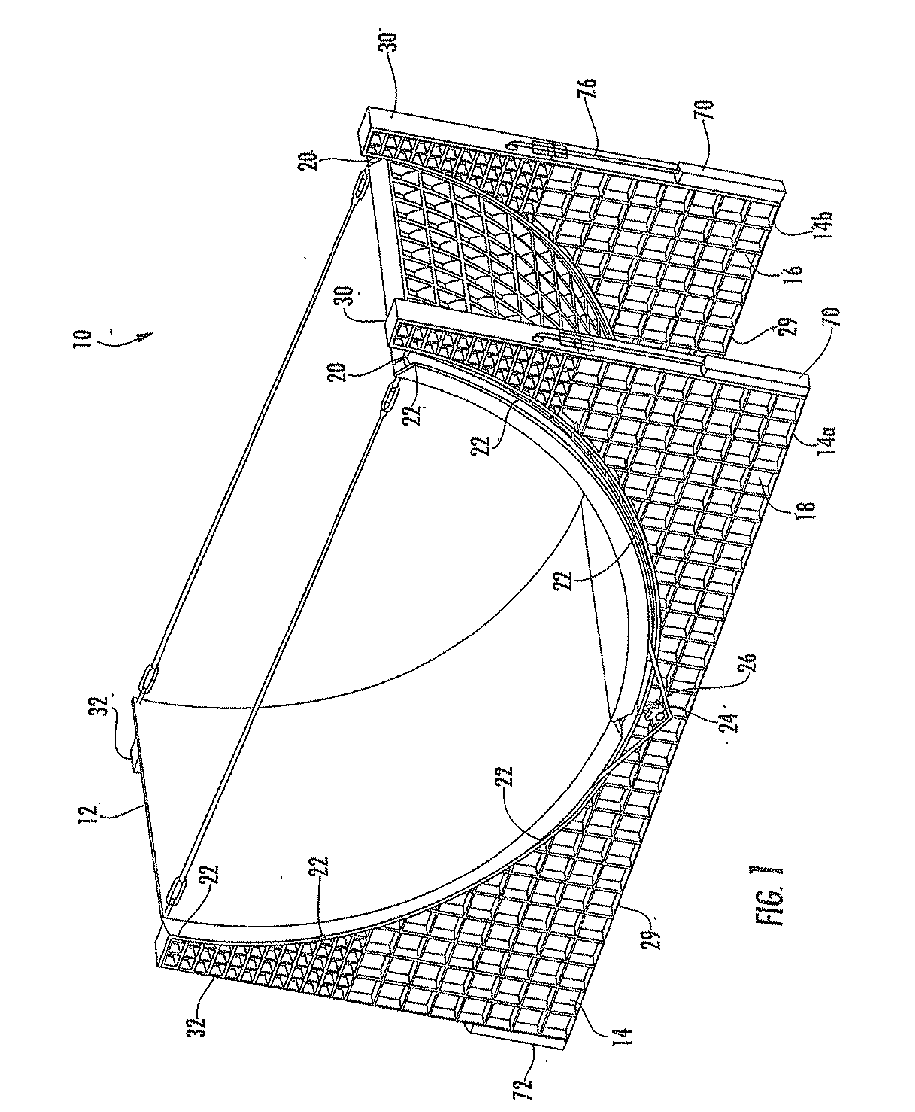
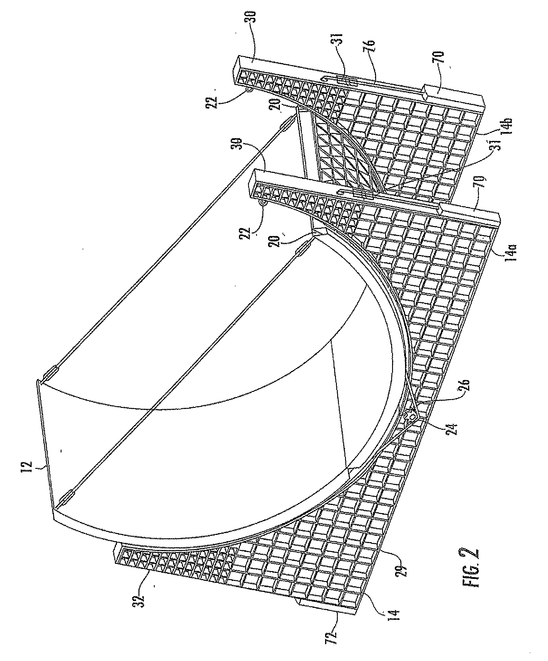
[0026]Referring initially to FIG. 1, a solar energy collector apparatus 10 comprises a solar collector panel 12 carried by a base 14. The solar collector panel 12 has a parabolic shape. The base 14 includes a pair of spaced apart support frames 14a, 14b. The support frames 14a, 14b are symmetrical to one another. In addition, each support frame 14a, 14b may be symmetrical to itself.

[0027]Each support frame 14a, 14b has an inner surface 16 and an outer surf...


PUM


Abstract

A solar energy collector apparatus includes a solar collector panel having a parabolic shape, and a base comprising a pair of spaced apart support frames. Each support frame has a parabolic shape corresponding to the parabolic shape of the solar collector panel. Spaced apart rollers are positioned along an upper surface of each support frame to support the solar collector panel. A drive mechanism is coupled to the solar collector panel for rotation thereof. The solar collector panel includes a pair of spaced apart guide channels on an underside thereof for contacting the spaced apart rollers to insure that the solar collector panel rotates squarely with respect to the base.

Description

RELATED APPLICATIONS [0001]This application claims the benefit of U.S. Provisional Application Ser. No. 61 / 138,287 filed Dec. 17, 2009, the entire contents of which are incorporated herein by reference.FIELD OF THE INVENTION [0002]The present invention relates to the field of solar energy collectors, and more particularly, to a parabolic solar energy collector.BACKGROUND OF THE INVENTION[0003]There are a variety of solar energy collectors available for converting solar energy into other forms of energy that can be more readily used or stored. These apparatuses typically employ solar collectors that collect solar radiation and convert it into a more useable form of energy, such as heat.[0004]Solar collectors of the flat plate type have been used in low energy applications such as heating water, generating low pressure steam, supplementing air conditioning and heating systems, and the like. Flat plate collectors do not focus the sun's radiation and have limited applicability.[0005]Ano...

Claims


Application Information

Patent Timeline
Patent Type & Authority Applications(United States)
IPC IPC(8): F24J2/40F24J2/02F24J2/38F24S20/20F24S20/30F24S23/70F24S23/74F24S50/20
CPCF24J2/07F24J2/14F24J2/5237F24J2/541F24J2002/0084Y02E10/47F24J2002/5458F24J2002/5462F24J2002/5475Y02E10/41Y02E10/45F24J2002/4692F24S20/20F24S23/74F24S25/11F24S30/425F24S2020/16F24S2030/133F24S2030/134F24S2030/14F24S2080/015Y02E10/40
Inventor POLK, SR., DALE E.POLK, JR., DALE E.
Owner D & D MFG
Why Eureka
Try Eureka