Panel connection system and a method of using the same

a technology of connection system and panel, which is applied in the direction of machines/engines, mechanical apparatus, liquid fuel engines, etc., can solve the problems of affecting the effectiveness of air supply, complicated assembly, and mechanical complexity, and achieve the effect of simple panel connection assembly, cost-effective manufacturing, and simple assembly and maintenan

Inactive Publication Date: 2017-08-22
ROLLS ROYCE PLC
View PDF19 Cites 0 Cited by
  • Summary
  • Abstract
  • Description
  • Claims
  • Application Information

AI Technical Summary

Benefits of technology

[0016]By forming the hanger plate and the first and second locating plates from sheet material, the panel connection assembly of the invention is simple and cost effective to manufacture. It is also straightforward to assemble and maintain. This makes the assembly attractive to a user.
[0046]It may therefore be necessary or desirable to circulate a cooling air or gas flow between the panel and the casing. By aligning the plurality of connection assemblies so that the hanger plates are all coplanar it is possible to minimise the flow disturbance caused by the connection assemblies. This makes the system of the invention more efficient and so more attractive to a user.

Problems solved by technology

Such mounting arrangements are required to accommodate movement of the duct both axially and laterally and can be mechanically complicated.
Previous jet pipe liner hanger systems have used expensive machined parts to control exhaust duct liner location and require a high number of part variations, making the assembly complicated.
Furthermore, large numbers of hangers can obstruct the airflow passing between surfaces, impacting the effectiveness of the air supply.

Method used


Image

  • Panel connection system and a method of using the same
  • Panel connection system and a method of using the same
  • Panel connection system and a method of using the same

Examples


first embodiment

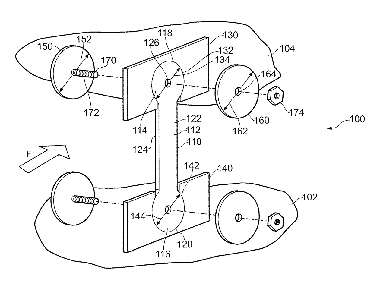
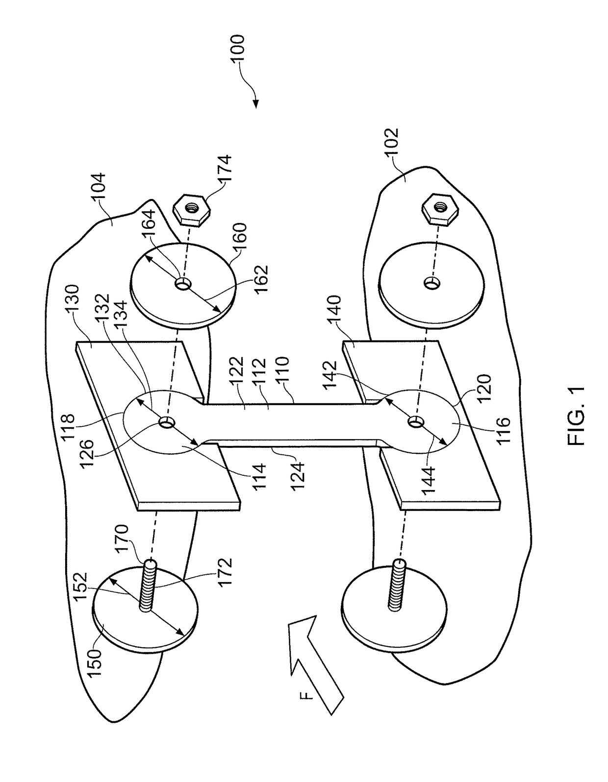
[0063]Referring to FIG. 1, a panel connection assembly according to the invention is designated generally by the reference numeral 100. The panel connection assembly 100 is intended for use in connecting a panel 102 to a casing 104. In the particular embodiments described below the panel 102 is an exhaust system (not shown) of a gas turbine engine (not shown) for use in an aerospace application, for example as an aircraft powerplant. The exhaust gas flow F is indicated by an correspondingly marked arrow in the figures.

[0064]The panel connection assembly 100 comprises a hanger plate 110, a first locating plate 130 and a second locating plate 140. The hanger plate 110 comprises an elongate body portion 112, a first end portion 114 and an opposite second end portion 116. Each of the first end portion 114 and the second end portion 116 has a circular profile 118,120. Consequently, the hanger plate 110 has a dumbbell shape.

[0065]The hanger plate 110 is made from a sheet metal stamping or...

second embodiment

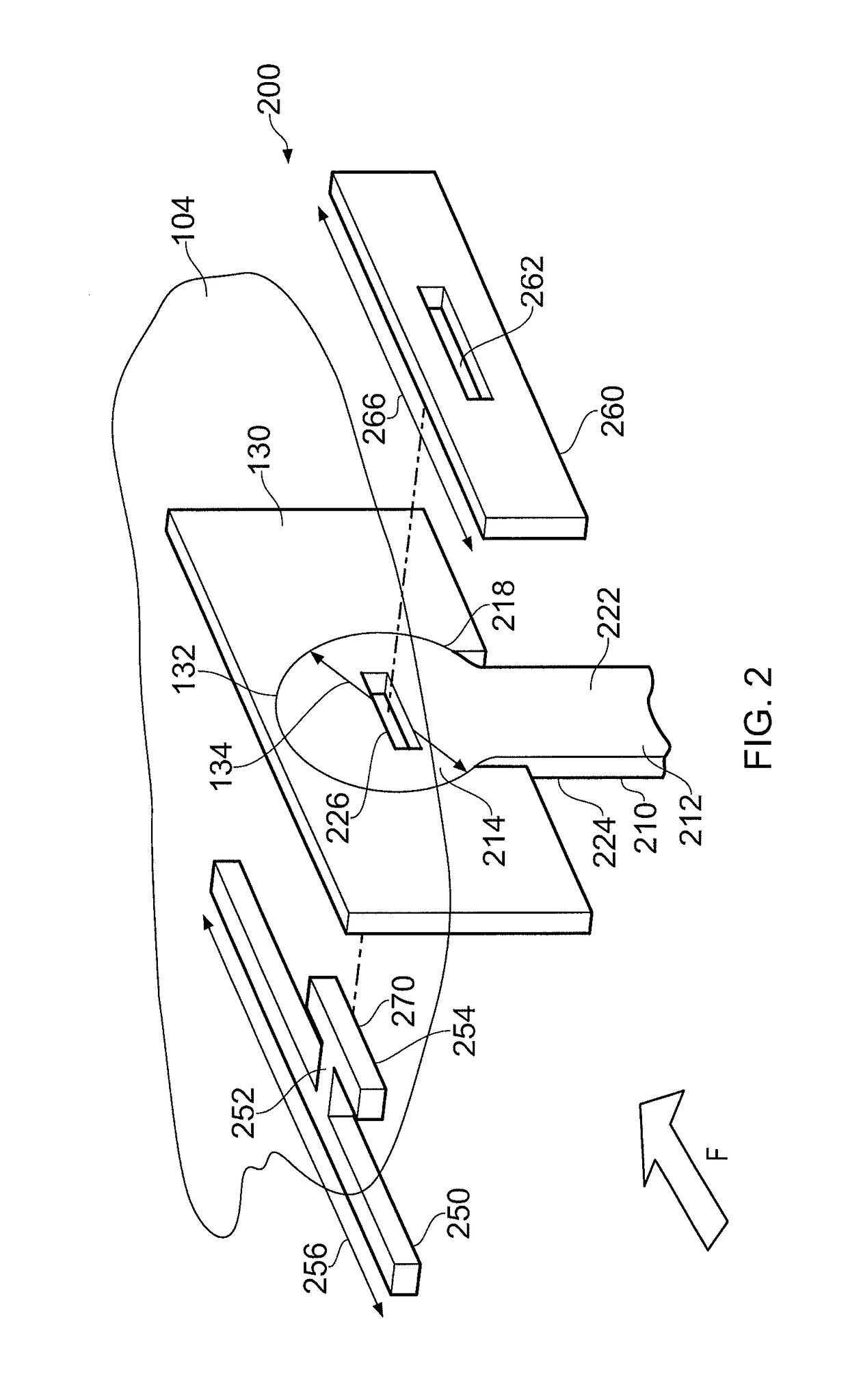
[0081]Referring to FIGS. 2 and 3, a panel connection assembly according to the invention is designated generally by the reference numeral 200. Features of the apparatus 200 which correspond to those of apparatus 100 have been given corresponding reference numerals for ease of reference.

[0082]The panel connection assembly 200 comprises a hanger plate 210, a first locating plate 130 and a second locating plate 140. The hanger plate 210 comprises an elongate body portion 212, a first end portion 214 and an opposite second end portion 216. Each of the first end portion 214 and the second end portion 216 has a circular profile 218,220. Consequently, the hanger plate 210 has a dumbbell shape.

[0083]The structure and function of the first and second locating plates 130,140 are identical to that described above with regard to the first embodiment of the invention.

[0084]The hanger plate 210 has a first surface 222 and an opposite second surface 224.

[0085]Each of the first end portion 214 and ...

third embodiment

[0093]Referring to FIGS. 4, 5 and 6, a panel connection assembly according to the invention is designated generally by the reference numeral 300. Features of the apparatus 300 which correspond to those of apparatus 100 have been given corresponding reference numerals for ease of reference.

[0094]The panel connection assembly 300 corresponds closely to the panel connection assembly 200 with some minor differences that are described below.

[0095]The differences between the panel connection assembly 300 and the panel connection assembly 200 relate to the geometry of the first and second retaining plates 350,360.

[0096]In this embodiment the distal portions of each of the first and second retaining plates 350,360 are laterally thinned where they extend over the surface of the corresponding first and second locating plates 330,340.

[0097]This feature allows the hanger plate 310 to pivot in the ‘out of plane’ direction as shown in FIG. 7. This movement enables the panel connection assembly 30...


PUM


Abstract

A panel connection assembly connects a panel to a casing including hanger, first locating, and second locating plates. The hanger plate has elongate body, first end, and opposite second end portions, with each of the first and second end portions having a circular profile. The hanger plate has a dumbbell shape. The first locating plate has a first circular locating aperture, the first locating aperture to accommodate the first end portion, and the second locating plate has a second circular locating aperture, the second locating aperture to accommodate the second end portion. In use, the first locating plate is secured to the casing, the second locating plate is secured to the panel, the first and second end portions are respectively accommodated within the first and second locating apertures with the elongate body portions extending therefrom, to connect the panel to the casing.

Description

[0001]This disclosure claims the benefit of UK Patent Application No. 1406630.2, filed on 14 Apr. 2014, which is hereby incorporated herein in its entirety.FIELD OF THE INVENTION[0002]The present invention relates to a panel connection system and particularly, but not exclusively, to a panel connection system for an exhaust gas duct.BACKGROUND TO THE INVENTION[0003]The exhaust duct for a gas turbine engine is conventionally a circular duct which connects to the turbine stage outlet of the engine. The use of a circular duct is convenient since it can be readily connected to the turbine outlet of the engine. In addition, thermal expansion of the exhaust duct resulting from the heat of the exhaust gas flow may be readily accommodated by the radial growth of the exhaust duct.[0004]However, in many gas turbine engine installations it is desirable for the exit portion of the exhaust duct to be non-circular because this can make the mechanical installation of the exhaust duct into its supp...

Claims


Application Information

Patent Timeline
Patent Type & Authority Patents(United States)
IPC IPC(8): F01D25/24F02K1/80F04D29/40
CPCF01D25/24F02K1/80F04D29/403F05D2260/941Y02T50/672Y02T50/60F02C7/20F02K1/04F02K1/82F05D2240/91
Inventor HAYTON, PAUL ROBERT
Owner ROLLS ROYCE PLC
Why Eureka
Try Eureka